When it comes to tackling the challenges of clearing pathways during colder months, it’s essential to be familiar with the inner workings of the machines that help us handle heavy snow. A well-maintained piece of equipment ensures smooth operation and longevity, especially when it’s built for handling harsh conditions. Being aware of how different elements function together not only improves performance but also prevents potential issues from arising over time.
Each component plays a critical role in ensuring that your winter machinery operates at its best. From the intricate mechanisms that power movement to the essential parts responsible for clearing away snow, understanding how these pieces connect and support each other allows for better maintenance and troubleshooting. This section will break down the key elements, offering insights into their purpose and how they contribute to overall efficiency.
Maintaining your equipment is key to its longevity and reliability. Knowing what to look for and understanding the various elements involved will help you spot wear and tear before it becomes a significant issue. In the following sections, we will delve deeper int
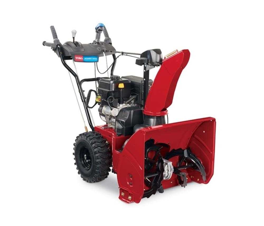
Essential Components of Toro 824 Snowblower
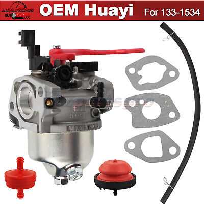
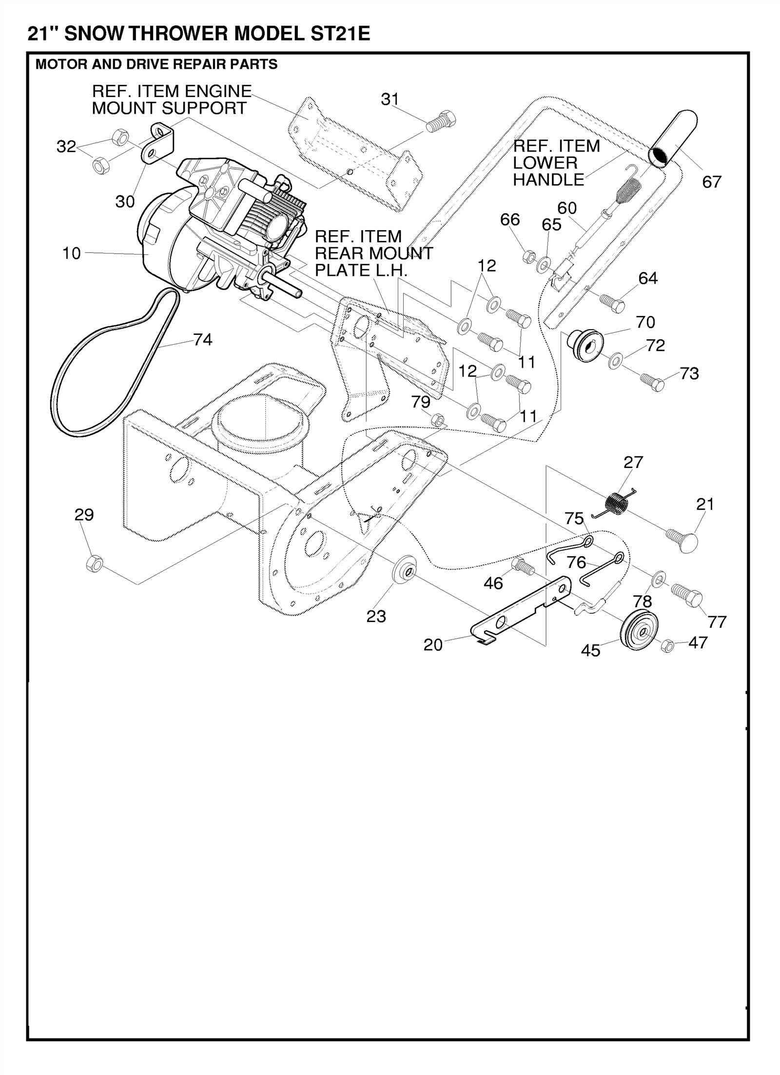
Understanding the key elements of this machine is crucial for effective operation and maintenance. Each section works together to ensure smooth functionality and reliable performance during heavy-duty tasks, especially in harsh conditions. Below, you will find a breakdown of the most significant mechanisms, providing insight into their roles and how they interact.
| Component | Description | |||||||||||||||
|---|---|---|---|---|---|---|---|---|---|---|---|---|---|---|---|---|
| Engine | The powerhouse that drives the entire system, converting fuel into mechanical force to tackle even the toughest tasks. | |||||||||||||||
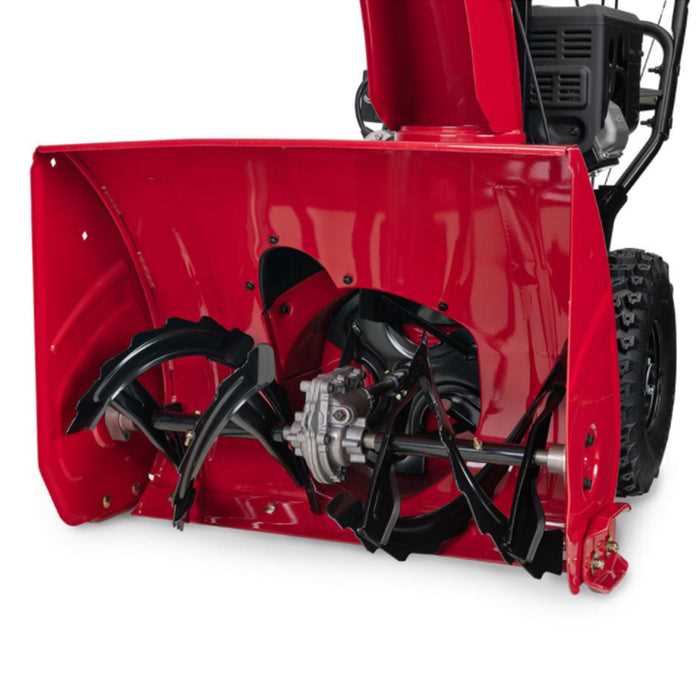
| Auger System | A set of rotating blades designed to gather materials and direct them into the chute for efficient expulsion. |
| Component | Function | Location | ||||||||||||||
|---|---|---|---|---|---|---|---|---|---|---|---|---|---|---|---|---|
| Belt | Transfers power from the motor to the drive mechanisms | Between the engine and pulley system | ||||||||||||||
| Pulley | Helps redirect and manage the tension of the belts | Near the engine output | ||||||||||||||
| Gearbox | Adjusts speed and tor
Auger Assembly and Its Functionality
The auger system plays a critical role in efficiently moving large quantities of snow, making the entire process more effective. By rotating at a controlled speed, it collects and channels the snow towards the discharge area, ensuring smooth and continuous clearing. Primary Components
The mechanism consists of several key parts that work together to achieve its purpose. The rotating blades are driven by a central shaft, designed to cut through packed layers. Additionally, gears and bushings provide the necessary support, allowing the blades to move seamlessly without excessive wear. Proper synchronization between these elements is crucial for optimal performance. Importance of Maintenance
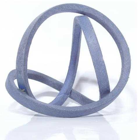
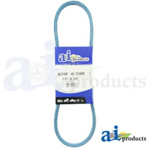
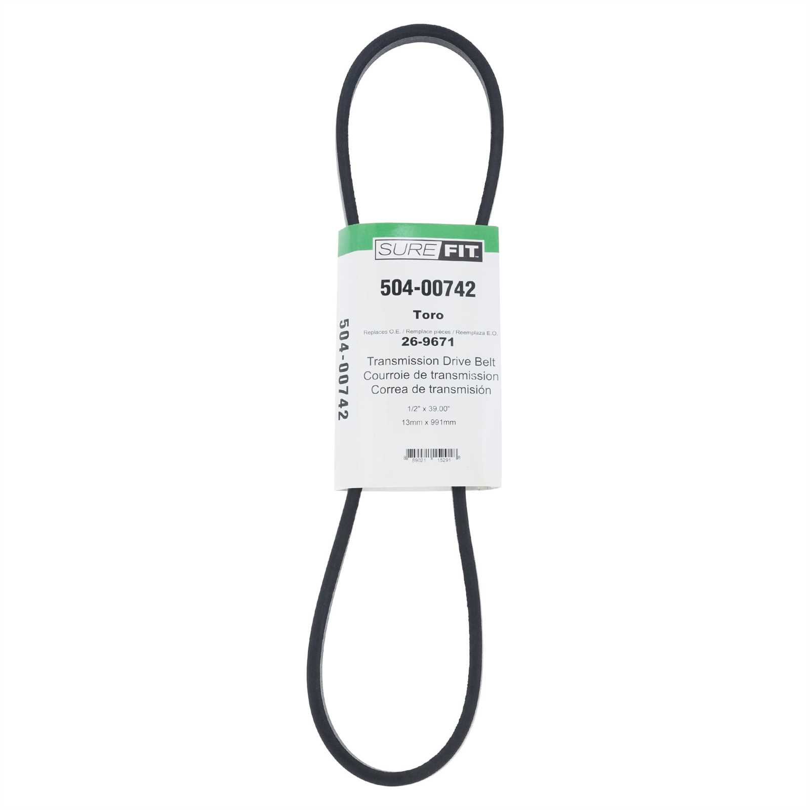
Regular inspection of the assembly ensures that it continues to function as intended. Over time, components such as blades and bearings can wear down, which may reduce efficiency. By addressing wear and tear early, you can maintain smooth operation and extend the overall lifespan of the machinery. Lubrication and occasional part replacement are essential practices to keep the auger in top condition. Role of the Impeller in Snow RemovalThe impeller plays a crucial function in efficient snow displacement by rapidly moving collected material out of the machine. Its rotating blades enhance the overall performance, ensuring that snow is directed away from the clearing path. This mechanism is responsible for the final stage of snow ejection, propelling it through a chute and creating a clean surface. Speed and force generated by the impeller are key to its effectiveness. As it spins, the impeller boosts the velocity of the gathered snow, allowing it to be thrown a significant distance. The power behind this rotation ensures that the cleared area remains free of obstructions, contributing to a smoother removal process. Blade design and construction also affect how well the impeller functions. The angle and curvature of each blade help to guide the snow efficiently, preventing blockages and maintaining continuous flow. These features ensure that even large amounts of snow can be managed effectively, allowing for consistent operation. Belts and Pulleys: Ensuring Smooth OperationIn any machine designed for heavy-duty tasks, the seamless interaction between components is crucial for optimal performance. Belts and pulleys are essential for transferring motion and power from one part to another, ensuring the equipment operates smoothly. Proper maintenance and timely replacements of these elements help prevent breakdowns and maintain efficiency during use. Understanding the Function of Belts
Belts act as the critical link that transmits force between rotating parts. They are responsible for maintaining synchronization between different moving elements, such as the engine and the auger or other related components. A well-maintained belt ensures that energy is transferred effectively, preventing unnecessary strain on the system. Pulleys: The Heart of Power Transfer
Pulleys play a vital role in guiding and directing the belt’s movement. They help increase or decrease the speed and torque, adapting to the machine’s operational needs. If pulleys become worn or misaligned, it can lead to inefficient power transfer and cause premature wear on both the belts and other connected parts. Regular inspection and adjustment of both belts and pulleys will greatly enhance the lifespan and functionality of the equipment. Keep these components in good condition to ensure uninterrupted performance and avoid costly repairs. Chute System Overview and Adjustments
The chute system plays a critical role in controlling the direction and distance of the thrown material. Proper adjustment ensures efficient operation, allowing for optimal performance in various conditions. The system consists of several key components that guide and direct the flow, with flexibility to modify the trajectory as needed for different tasks. Key ComponentsThe chute is made up of a rotating part and a directional mechanism, which work together to provide smooth movement and precise control. By adjusting the angle or rotation, operators can direct the expelled material with accuracy. Regular maintenance of these components ensures they remain free from obstructions and function properly throughout the season. Making Adjustments
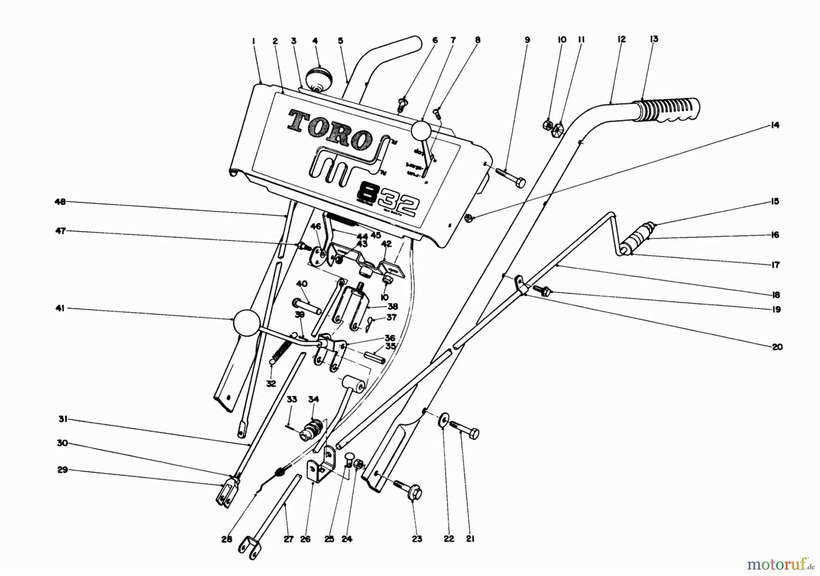
To adjust the chute system, first ensure all moving parts are properly lubricated and free of debris. Adjusting the angle of the chute allows you to control the distance, while rotating it adjusts the direction of the material. Fine-tuning these settings will improve efficiency and reduce the need for manual corrections during use. Handle Controls and Operational FeaturesThe handle controls are vital components in ensuring the efficient operation of outdoor clearing equipment. These features enable the user to manage movement, power, and other essential functions, all while maintaining ease of use and comfort. A well-designed control system provides intuitive access to key settings, allowing for a smooth and effective experience during operation.
Maintaining Safety Mechanisms and Shields
Ensuring the proper functioning of protective components is crucial to prevent accidents and enhance the efficiency of equipment. Regular checks and maintenance of these features can prevent malfunctions that may lead to potential risks. These safety systems are designed to shield users from moving parts and hazardous materials, providing a safer operation environment. By keeping these elements in optimal condition, you ensure both safety and longevity of the machinery.
|
