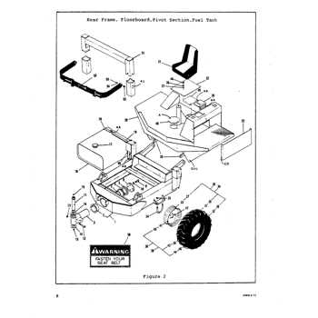
Understanding the structure and organization of essential components in any mechanical system is crucial for ensuring smooth operation and maintenance. This section provides a detailed exploration of the key elements, focusing on how they interconnect to deliver optimal performance. By examining each part closely, we can better grasp the intricate design and the functional relationships between various mechanisms.
Whether for routine upkeep or troubleshooting, having a clear view of the entire assembly is invaluable. This breakdown will help users efficiently identify and locate necessary elements, ensuring proper handling and potential replacement when needed. Exploring the arrangement of the individual sections will empower users to maintain their equipment with greater confidence and ease.
In this guide, you’ll find an in-depth explanation of each crucial element, offering insights into its role within the system. By paying close attention to the layout, users can gain a deeper understanding of the machine’s overall functionality, paving the way for more effective operation and care.
Understanding the Wright Stander 52 Design
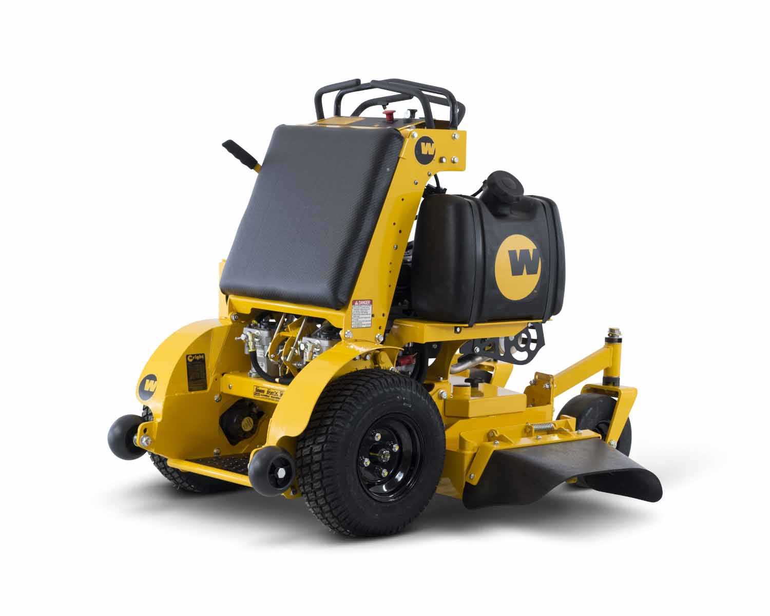
The structure of this specific model offers an efficient and compact framework that enhances performance in various terrains. Its layout has been carefully engineered to ensure both stability and ease of operation, providing users with a seamless experience. The thoughtful placement of components contributes to improved maneuverability, allowing for precise control during use.
Key elements of this design focus on the balance between weight distribution and ergonomic functionality. By emphasizing user comfort and accessibility, the layout promotes prolonged operation without compromising on effectiveness. Moreover, the optimized arrangement of essential parts helps in reducing wear and tear, ensuring longevity and reliability in demanding environments.
Key Components of the 52-Inch Model
The 52-inch model consists of essential mechanical and structural elements designed to ensure efficiency and performance. This section highlights the main components that are integral to its functionality, focusing on their roles and contributions to the overall system.
Primary Structural Elements
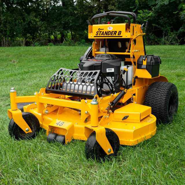
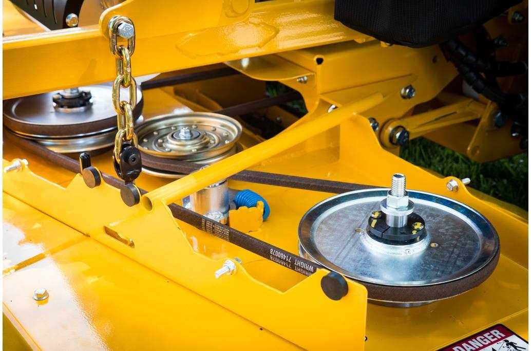
The frame forms the foundation of the unit, providing stability and support for all other components. Reinforced with durable materials, it is built to withstand regular use. The cutting mechanism, which includes multiple blades, plays a crucial role in delivering a precise cut, maintaining consistency and quality during operation.
Mechanical and Control Systems

The drive system controls the movement and speed, ensuring smooth operation across varied surfaces. Additionally, the control panel is designed for ease of use, allowing the operator to adjust settings with precision. These systems work together to optimize both maneuverability and efficiency.
| Component | Function | ||||||||||||||
|---|---|---|---|---|---|---|---|---|---|---|---|---|---|---|---|
Frame
Engine and Power System BreakdownThe power unit and propulsion system are crucial components that ensure the machine operates efficiently and smoothly. Understanding how these elements work together is key for maintaining performance and longevity. The power source, combined with the various mechanical parts, delivers the necessary energy to drive the entire system. Below is an overview of the primary elements and their functions:
Steering and Control Mechanisms OverviewEffective navigation and control systems are essential for managing machinery in dynamic working environments. These mechanisms ensure smooth operation and enable precise handling, making it easier to maneuver in tight spaces and varied terrain. Understanding the setup and functionality of these systems is key to maintaining operational efficiency. Key Components of the Steering System
Control Mechanisms and AdjustabilityThe control mechanisms allow operators to modify speed, direction, and other critical parameters. They often include:
Cutting Deck Structure and Features
The design of the cutting deck plays a vital role in the overall performance and efficiency of any mowing system. Its construction is engineered to provide durability, precision, and smooth operation while maintaining consistent results during use. By carefully integrating various components, the deck ensures balanced cutting and optimized grass dispersal. Reinforced Frame for StabilityA key aspect of the deck’s structure is its reinforced frame, which enhances durability and ensures long-lasting performance even under demanding conditions. The materials used are selected for their resistance to wear and their ability to support the smooth movement of the blades without compromising on precision. Blade Design and Placement
The arrangement and design of the blades within the deck are optimized to deliver an even cut. Each blade is strategically positioned to cover the entire cutting width, allowing for efficient grass removal and minimizing missed areas. This setup ensures that the mowing task is completed with precision and a consistent finish every time. Maintenance Tips for Essential PartsRegular upkeep of crucial components is vital for ensuring optimal performance and longevity. By adhering to a few simple guidelines, you can prevent wear and tear, enhancing the overall functionality of your equipment. Routine Checks
Timely Replacements
Common Wear and Replacement Parts
In any mechanical device, certain components are prone to wear over time due to regular usage. Understanding which elements are subject to fatigue and require periodic substitution is essential for maintaining optimal functionality and performance. This section explores frequently affected components and offers guidance on recognizing when replacements are necessary. Key Components to Monitor
Regular inspection of specific elements can prevent significant issues and enhance the longevity of the equipment. The following list highlights crucial components that may experience wear and tear:
Maintenance TipsTo ensure the equipment functions efficiently, regular maintenance should be performed. This includes cleaning, lubrication, and timely replacement of worn-out components. Keeping a maintenance schedule can help identify potential issues before they escalate, ensuring smooth operation and extending the lifespan of the machinery. Safety Mechanisms and Protective Features
Ensuring user security is a fundamental aspect of any equipment design. Various features are implemented to enhance safety during operation, protecting both the user and the device. These mechanisms are crucial for preventing accidents and ensuring reliable performance in various conditions. Key safety measures include:
Incorporating these protective elements not only increases safety but also boosts user confidence, allowing for more effective and worry-free operation. Hydraulic System Function and Care
The hydraulic system plays a crucial role in the overall performance and efficiency of various machinery. This system operates by transferring fluid to generate force, enabling the equipment to execute heavy lifting and precise movements with ease. To ensure optimal functioning, regular maintenance and care are essential. Here are some key aspects to consider:
By adhering to these practices, operators can prolong the life of the hydraulic system and maintain the efficiency of the equipment. Regular attention to these details will contribute significantly to the overall reliability and productivity of the machinery. |
