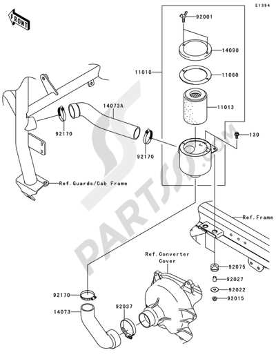
Understanding the layout and key components of an all-terrain utility vehicle is crucial for ensuring its proper maintenance and performance. Whether you are performing routine checks or addressing specific issues, having a clear view of the structure and its main elements helps you navigate the system effectively.
In this section, you will find a detailed overview of various mechanical and electrical elements that make up a utility transport model. We will delve into the intricate design, focusing on how different systems and modules interact and function together. By examining each element’s role, you gain insight into how to efficiently maintain, repair, and optimize the vehicle for your specific needs.
From the engine assembly to the transmission setup, each component plays a critical role in overall performance. This guide provides a thorough breakdown of the layout, offering essential knowledge that can
Essential Components of the Kawasaki Mule 4010
This section provides an overview of the critical elements that ensure the optimal functioning and reliability of this utility vehicle. Understanding these components is crucial for proper maintenance and efficient operation.
The engine is the powerhouse, delivering the necessary performance for both work and recreation. The transmission system works in harmony with the engine, enabling smooth shifting and power distribution. The suspension setup offers stability and comfort, ensuring the vehicle can navigate various terrains with ease.
Another vital aspect is the braking system, designed for responsive stopping power under different conditions. The steering mechanism ensures precise control, allowing the operator to maneuver safely. The electrical components, including the battery and wiring, support the various systems and features integrated into the vehicle.
Finally, the frame and chassis provide structural support, maintaining the integrity and durability required for heavy-duty use. These foundational parts work together, contributing to the vehicle’s performance and reliability.
Understanding the Engine Assembly Layout
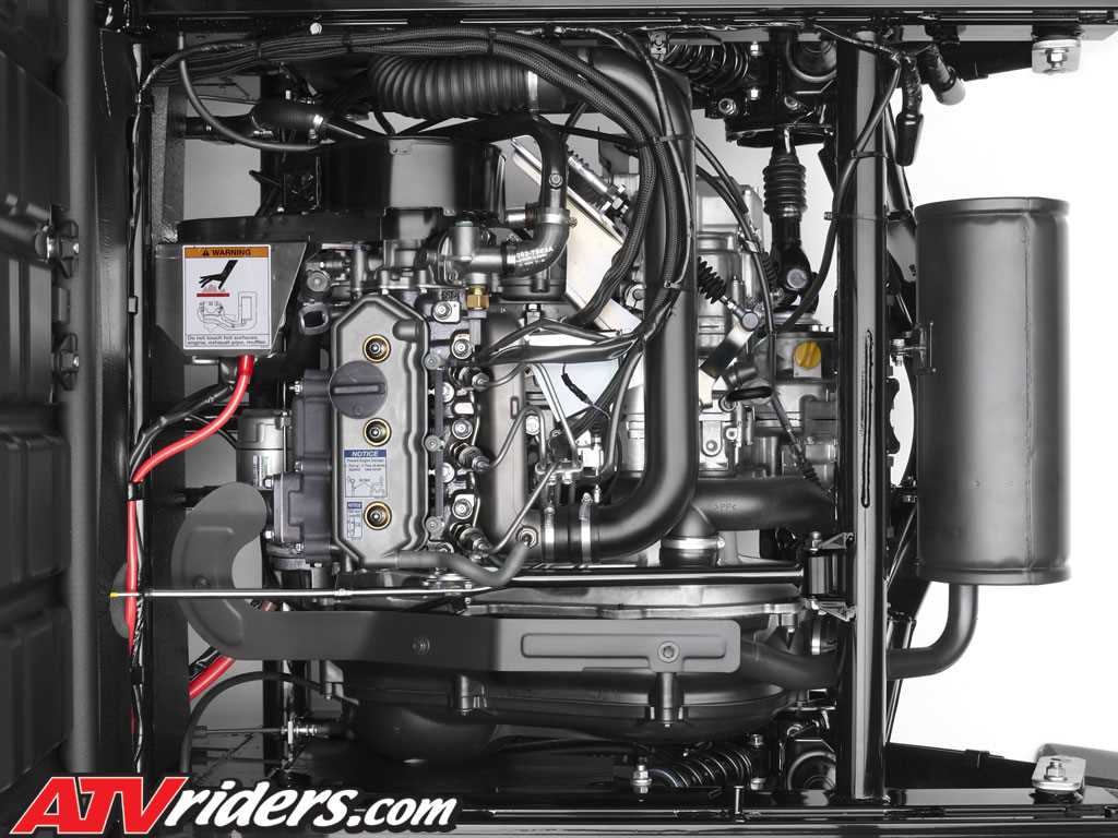
The engine assembly layout is crucial for maintaining and repairing your vehicle’s power unit efficiently. Knowing the arrangement and how each component interacts can help identify issues, perform routine checks, and understand the mechanics behind the operation. This section provides a detailed overview of the engine’s construction and component placement, offering a clearer picture of its overall structure.
Main Components Overview
The core of the engine assembly includes essential elements such as the cylinder block, pistons, and crankshaft. These parts work together to convert fuel into mechanical energy, powering the entire system. The cylinder block houses the pistons, which move up and down as the crankshaft rotates, creating the necessary motion to drive the vehicle. Additionally, various smaller components such as gaskets, valves, and the camshaft are strategically positioned to ensure smooth operation and efficiency.
Fluid Systems and Connections
Transmission System and Its Main Parts
The transmission mechanism plays a crucial role in managing the distribution of power from the engine to the wheels. It ensures that the vehicle operates smoothly under various conditions, adjusting power levels and speed to match the terrain and load requirements. This section provides an overview of the system’s components and their functions.
Main Components
The transmission setup is composed of several vital elements, each designed to handle specific tasks within the power delivery process. Below is a breakdown of the key components involved:
- Gearbox: The central unit responsible for controlling the gear ratios, allowing for efficient speed and torque adjustments based on driving needs.
- Clutch Assembly: Engages and disengages the power flow from the engine, permitting smooth shifting between gears without causing damage.
- Drive Shafts: Transmit the rotational energy from the gearbox to the wheels
Suspension and Steering Mechanism Overview
The suspension and steering system is designed to provide stability, control, and comfort during various driving conditions. This section will describe the components and functions of these systems, focusing on how they work together to ensure smooth and safe maneuvering over different terrains.
Key Components of the Suspension System
The suspension system consists of several elements that work together to absorb shocks and maintain vehicle balance. Below is an outline of the main components:
- Shock Absorbers: These dampen the impact from uneven surfaces, ensuring a comfortable ride.
- Springs: Work alongside shock absorbers to support the vehicle’s weight and maintain height.
- Control Arms: Connect the wheels to the chassis, allowing for controlled vertical movement.
- Stabilizer Bar: Reduces body roll during cornering by distributing weight evenly.
- Check Coolant Levels: Regularly inspect the coolant levels in the reservoir and top off as needed to ensure proper circulation.
- Inspect for Leaks: Look for any signs of leakage around hoses, the radiator, and connections, as leaks can lead to overheating.
- Flush the System: Periodically flushing the cooling system helps remove contaminants and ensures the coolant remains effective.
- Examine Hoses: Check hoses for wear and tear; replace any that are cracked or brittle to prevent failures.
- Brake Pedal: The driver uses this mechanism to engage the braking system.
- Master Cylinder: This unit converts the force applied to the brake pedal into hydraulic pressure.
- Brake Lines: These tubes carry brake fluid from the master cylinder to the brake assembly at each wheel.
- Brake Calipers: These devices house the brake pads and create friction against the brake discs when engaged.
- Brake Pads: Made of friction material, these pads press against the discs to slow down the vehicle.
- Brake Discs: Rotating components that provide a surface for the brake pads to grip.
- Brake Shoes: Used in drum brake systems, these components press against the drum to create friction.
- Drum: The cylindrical component that rotates with the wheel, against which the brake shoes apply pressure.
- Material: Commonly made from steel or aluminum for strength and lightweight characteristics.
- Design: A tubular or ladder design that provides rigidity and support.
- Welds: Strong, reinforced joints that enhance overall structural integrity.
- Body Panels: Durable materials that protect internal components and provide an aesthetic finish.
- Sealing: Proper sealing techniques to prevent water and debris from entering critical areas.
- Access Points: Strategically placed doors and panels for maintenance and cargo access.
Electrical System Components and Functions
The electrical system is an essential part of any vehicle, responsible for managing and distributing power to various components. Understanding its structure and how each part interacts is crucial for maintaining and troubleshooting the system effectively. This section provides an overview of the key elements within the system and their respective roles.
Battery: The central power source, the battery supplies the necessary electricity to start the engine and operate other systems when the engine is not running. It stores energy and provides a steady current to various components.
Alternator: The alternator is responsible for generating electricity while the engine is running. It powers electrical systems and recharges the battery, ensuring that the vehicle has a continuous power supply during operation.
Cooling System Structure and Maintenance Tips
The cooling system is a critical component in ensuring optimal performance and longevity of the engine. It works by regulating the temperature of the engine, preventing overheating, and maintaining efficient operation. Understanding its structure and how to care for it can significantly enhance the lifespan of the machinery.
Structure of the Cooling System
This system typically comprises several key components, including a radiator, water pump, thermostat, and coolant passages. The radiator dissipates heat absorbed from the engine, while the water pump circulates the coolant throughout the system. The thermostat regulates the coolant flow based on temperature, ensuring the engine reaches and maintains its ideal operating temperature.
Maintenance Tips
Regular maintenance of the cooling system is essential for preventing issues. Here are some tips to consider:
By following these guidelines, you can maintain an efficient cooling system that contributes to the overall reliability and performance of your vehicle.
Brake System Parts and Their Arrangement
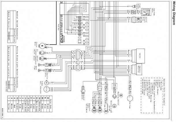
The braking system is a critical component of any vehicle, ensuring safety and control during operation. Understanding the various elements involved and their organization can significantly enhance maintenance and repair efforts.
Typically, the braking assembly consists of several key components:
Proper arrangement and maintenance of these components are essential for optimal braking performance. Regular inspections can prevent premature wear and ensure that each element functions effectively.
Fuel System Configuration and Diagrams
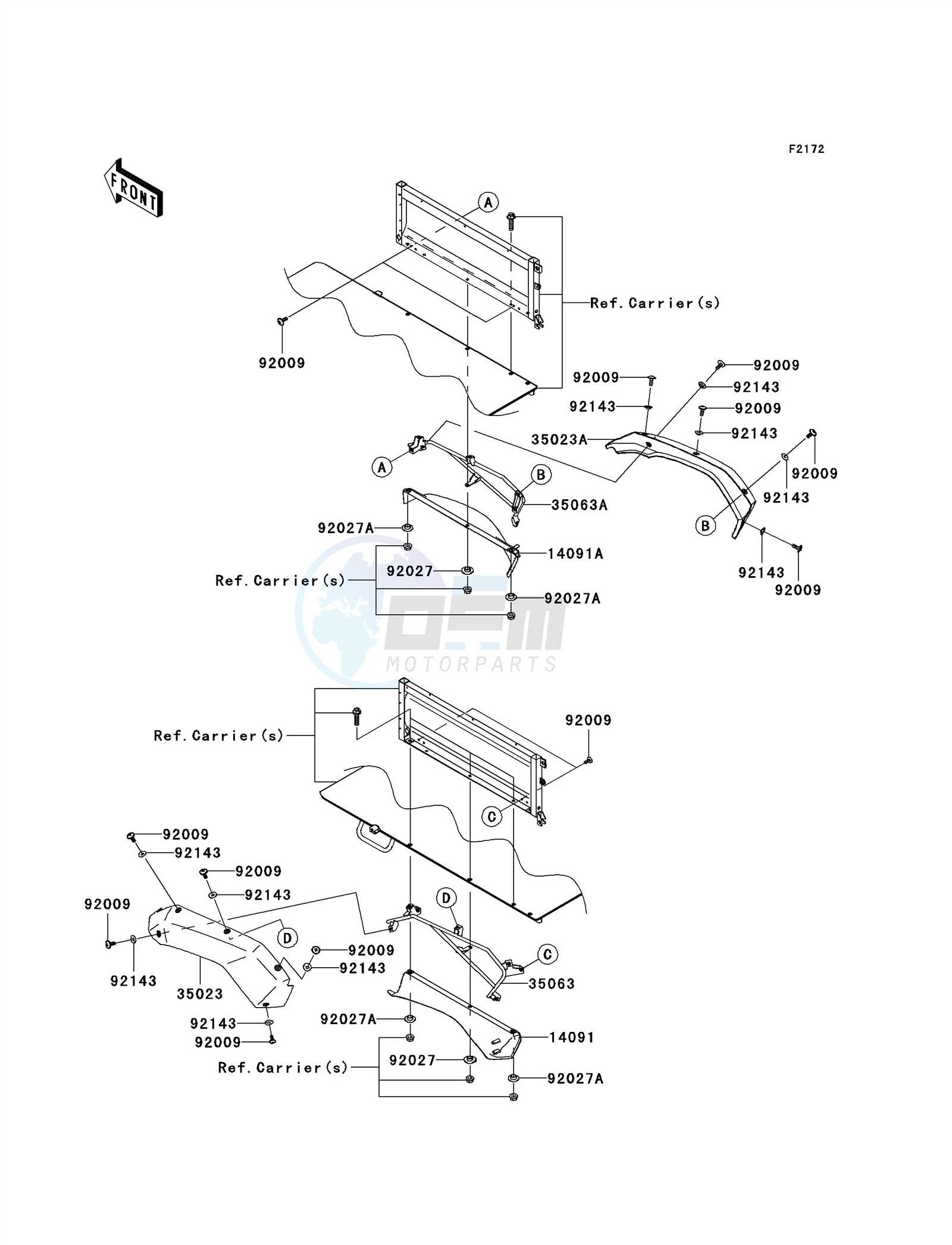
The fuel system is a crucial component of any engine, ensuring efficient delivery and management of fuel to optimize performance. Understanding its configuration and associated schematics can significantly aid in troubleshooting and maintenance. This section provides insights into the various elements of the fuel system and illustrates their interconnections through detailed diagrams.
Component Description Fuel Tank Stores the fuel required for engine operation. Fuel Pump Transfers fuel from the tank to the engine, maintaining adequate pressure. Fuel Filter Cleans the fuel before it enters the engine to prevent contamination. Fuel Injector Delivers precise amounts of fuel into the combustion chamber for optimal combustion. Fuel Lines Connect various components of the system, ensuring the flow of fuel. By analyzing the configuration and schematics of the fuel system, users can gain a deeper understanding of its functionality and make informed decisions regarding maintenance and repairs.
Frame and Body Structure Details
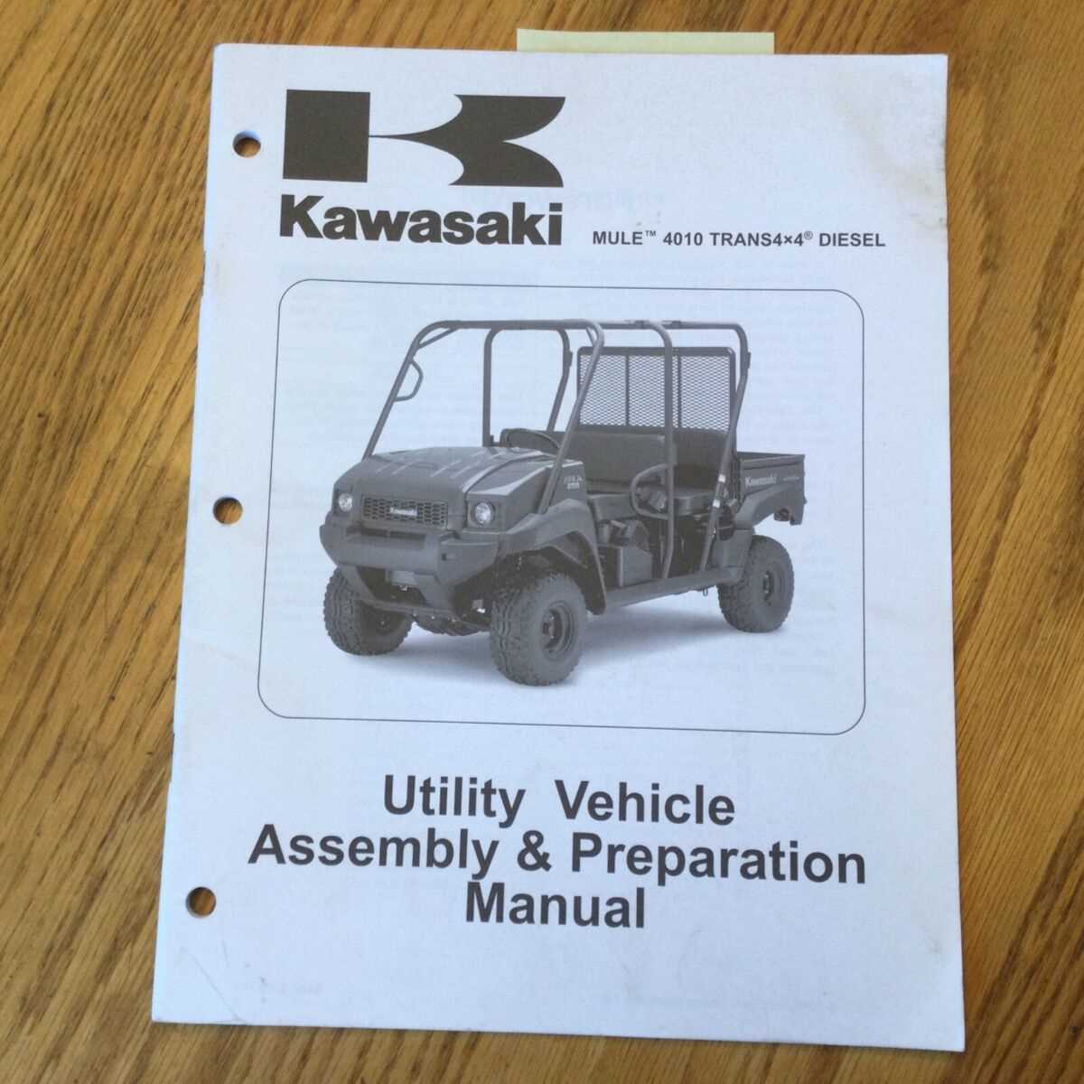
The frame and body structure of an all-terrain vehicle play a crucial role in its overall performance, stability, and durability. This section delves into the components and characteristics that contribute to a robust and functional design, ensuring the vehicle can withstand various terrains and conditions.
Frame Composition
The frame is typically constructed from high-strength materials designed to endure heavy loads and resist deformation. The following elements are key components of the frame:
Body Structure Features
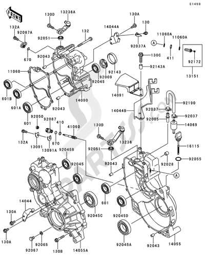
The body structure complements the frame, offering protection and utility. Key features include: