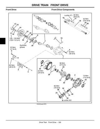
Understanding the structure and layout of essential vehicle elements can be invaluable for maintaining and troubleshooting a wide range of models. An organized guide can provide clarity when identifying each piece’s role within the system, ensuring optimal performance and reducing downtime. Familiarity with these internal layouts not only simplifies repair efforts but also enhances efficiency by helping users quickly pinpoint areas of concern.
For users involved in repairs or routine upkeep, a clear breakdown of these configurations is essential. The arrangement details cover aspects such as connectivity points, energy flow channels, and mechanical interactions. This knowledge is especially useful in determining compatibility and spotting any signs of wear or malfunction.
Our guide explores these foundational setups with precision, making it accessible for both seasoned technicians and casual users looking to deepen their understanding. By delving into the internal structure, users can anticipate maintenance needs, ensure compatibility with replacement elements, and maintain peak functionality over time.
Overview of John Deere Buck 500 Components
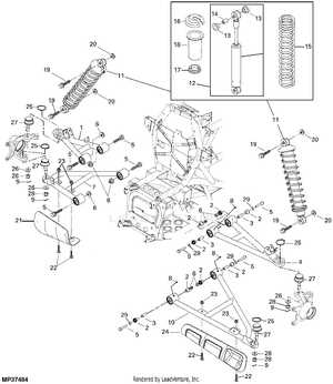
The layout of this vehicle’s mechanical and electronic elements brings together a balance of durability and efficiency, designed for handling various types of terrain and tasks. The assembly features a range of interconnected modules that work in unison to deliver consistent performance, from the core drive system to the supporting electrical components.
Each section, including the primary propulsion mechanisms and auxiliary systems, is arranged to support both power and adaptability, accommodating a wide array of uses. Critical segments of the vehicle are engineered to endure high usage, with an emphasis on resilience and ease of maintenance, contributing to its long-term reliability. This organization of components reflects careful planning to maximize functionality, making it versatile in challenging environments.
Overall, the unit’s construction prioritizes accessible maintenance and straightforward assembly, allowing operators to address wear and modifications efficiently. The integration of each part highlights a user-friendly approach that assists in enhancing longevity and simplifying upkeep, ensuring dependable operation across various conditions.
Understanding the Engine Assembly Layout
In order to grasp the overall structure of an engine’s assembly, it’s essential to familiarize oneself with the arrangement of its primary components and how they interact within the machinery. The engine layout showcases the positioning of essential parts like the combustion chamber, cooling system, and fuel injectors, each organized in a way that maximizes performance and efficiency.
The assembly is carefully designed to ensure smooth operation, reduce wear, and optimize power output. Key elements are strategically placed to facilitate maintenance, improve durability, and support overall functionality. With this understanding, anyone can better interpret the purpose and placement of each piece within the engine, aiding in upkeep and potential troubleshooting.
Key Electrical System Elements Explained
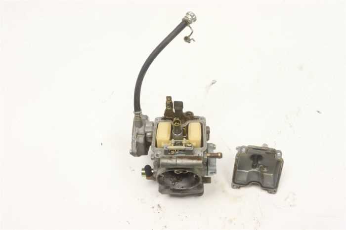
The electrical system in a vehicle plays a critical role in ensuring optimal performance and reliability. It encompasses a range of components that work together to supply power, control lighting, and support essential functions, making understanding its key elements vital for effective maintenance.
Power Distribution

The power distribution segment is responsible for transferring energy from the main power source to various vehicle parts. This includes connections to the battery, fuses, and relays, which help regulate and protect the flow of current. Proper alignment of these parts is crucial to prevent issues such as short circuits and power failures.
Control Units and Wiring
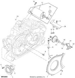
Control units serve as the brain of the electrical system, managing functions like ignition, lighting, and indicators. The wiring and connections that interlink these components ensure seamless operation and quick responses to user actions. Regular checks and maintenance of these units can help avoid malfunction and ensure efficient energy distribution.
Brake System Parts and Their Functions
In any vehicle, the braking mechanism is a crucial safety feature designed to manage and control stopping power effectively. This section provides an overview of the key components in the braking assembly, explaining their roles in ensuring reliable braking performance.
Main Components of the Braking Mechanism
- Brake Pedal: The starting point for the braking process, where pressure is applied by the operator’s foot to initiate a controlled halt.
- Brake Calipers: These devices press against the rotor when force is applied, causing friction that slows down the wheels.
- Brake Pads: Attached to the calipers, these pads grip the rotors to create the friction necessary for deceleration.
- Brake Rotors: Flat metal discs that rotate with the wheels, providing a surface for the brake pads to press against.
Additional Components Supporting Brake Functionality
Detailed View of the Transmission Assembly
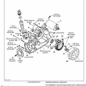
The transmission assembly is a crucial component that ensures efficient power transfer within the machinery, translating engine output into the motion needed for smooth operation. Understanding each part’s location and role within this system is essential for effective maintenance and troubleshooting.
Within the assembly, gears, shafts, and various connecting elements work in unison to manage speed adjustments and force distribution. Primary gears handle the initial power input, while secondary gears and output shafts manage speed and torque adjustments. Together, these elements create a balanced system that maintains consistent movement across various terrain types.
Each component within the transmission setup is designed to handle specific stress levels and torque loads, ensuring durability over prolonged use. Familiarizing oneself with the positioning of linkages and gear clusters can significantly aid in diagnosing potential issues and enhancing overall performance.
Suspension and Steering Mechanism Components
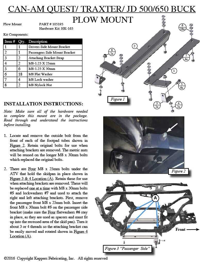
The suspension and steering systems are vital for ensuring a smooth and controlled driving experience. These components work together to provide stability, enhance maneuverability, and absorb shocks from uneven terrain. Understanding the various elements involved in these systems is essential for maintenance and troubleshooting.
- Shock Absorbers: These elements minimize the impact of bumps and dips in the road, enhancing ride comfort and vehicle control.
- Control Arms: These components connect the chassis to the wheel assemblies, allowing for controlled wheel movement during steering and suspension travel.
- Steering Rack: This device translates the driver’s input into wheel movement, playing a crucial role in steering responsiveness.
- Ball Joints: These flexible connectors enable the suspension system to move freely while maintaining stability and alignment.
- Struts: Serving as a structural component of the suspension, struts support the weight of the vehicle and provide damping.
In addition to these primary components, various links and brackets support the overall structure, ensuring proper alignment and function. Regular inspection of these systems is crucial to maintain optimal performance and safety.
Fuel System Configuration and Components
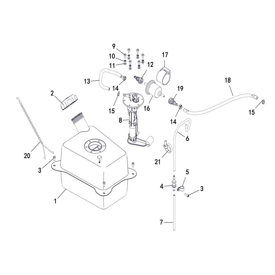
The efficient operation of any machinery relies heavily on its fuel system. This system is responsible for storing, filtering, and delivering the necessary energy source to the engine. Understanding the various elements involved can enhance maintenance practices and ensure optimal performance.
The main components of a typical fuel system include the tank, pump, filter, and injectors. Each part plays a critical role in ensuring that the fuel reaches the engine in the right condition and quantity.
| Component | Function |
|---|---|
| Fuel Tank | Stores the fuel until it is needed by the engine. |
| Fuel Pump | Transfers fuel from the tank to the engine. |
| Fuel Filter | Removes impurities and contaminants from the fuel. |
| Injectors | Atomizes the fuel for efficient combustion in the engine. |
Regular inspections and maintenance of these components are essential for preventing breakdowns and ensuring longevity. Understanding how each element contributes to the overall fuel system can aid in diagnosing potential issues and performing effective repairs.
Essential Cooling System Parts Overview
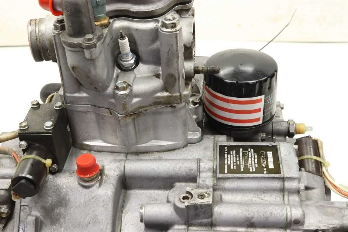
The efficiency of any machinery heavily relies on its ability to maintain optimal operating temperatures. A well-designed cooling system plays a crucial role in preventing overheating and ensuring smooth performance. Understanding the key components involved is essential for effective maintenance and troubleshooting.
The primary component of a cooling system is the radiator, which dissipates heat from the engine coolant. Alongside it, the water pump circulates coolant throughout the system, ensuring consistent temperature regulation. The thermostat regulates coolant flow, opening and closing based on temperature changes to maintain balance.
Additionally, hoses facilitate the movement of coolant between components, while the fan assists in airflow over the radiator to enhance heat exchange. Regular inspection and maintenance of these essential elements contribute significantly to the longevity and efficiency of the overall system.
Maintenance Tips for Common Parts
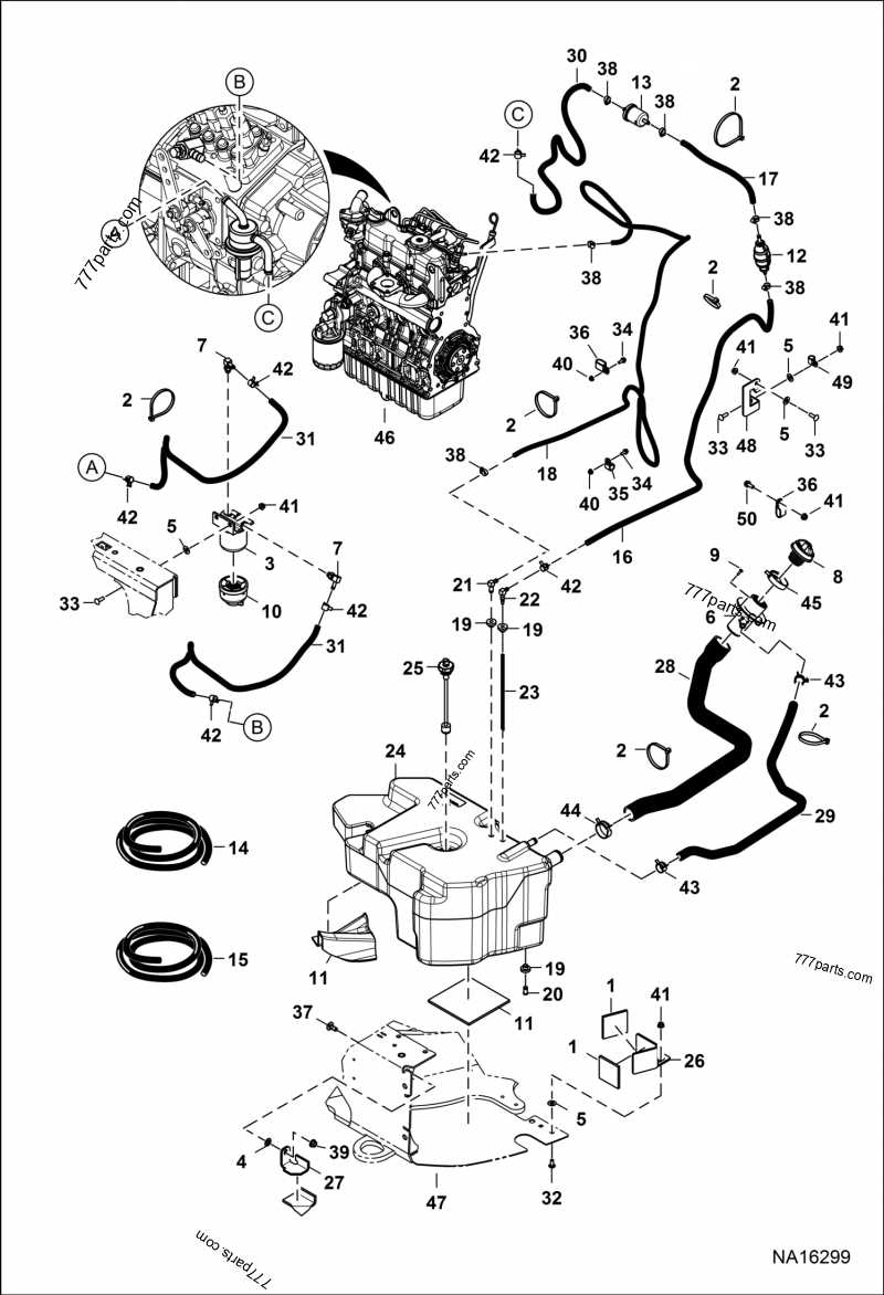
Proper upkeep of essential components is crucial for optimal performance and longevity of your machinery. Regular attention to these elements not only enhances efficiency but also prevents costly repairs in the future. Below are some valuable suggestions for maintaining frequently encountered elements in your equipment.
Regular Inspection
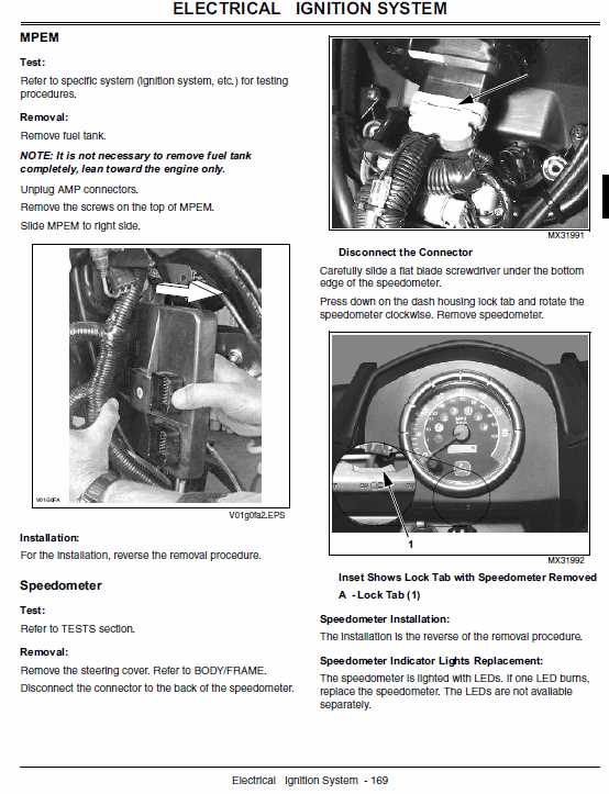
Conduct routine checks to identify signs of wear or damage. Early detection can help mitigate potential issues before they escalate. Focus on areas prone to stress and friction, ensuring they remain in good condition.
Lubrication and Cleaning
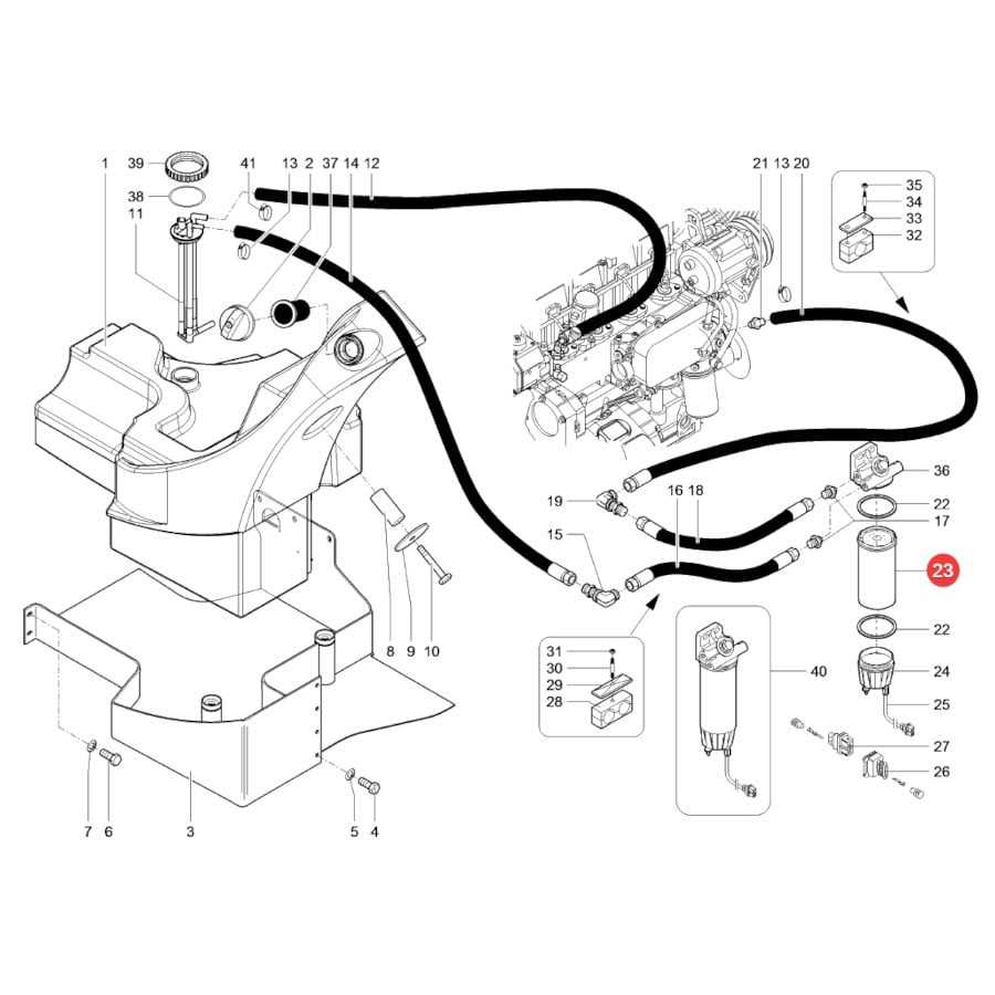
Keep moving components well-lubricated to minimize friction and heat buildup. Additionally, regular cleaning prevents the accumulation of dirt and debris, which can impede functionality. Use appropriate cleaning agents to maintain surface integrity.
| Component | Maintenance Task | Frequency |
|---|---|---|
| Belts | Inspect for cracks and fraying | Monthly |
| Filters | Replace as needed | Every 50 hours of operation |
| Fluids | Check and top off levels | Weekly |
| Batteries | Inspect for corrosion | Monthly |