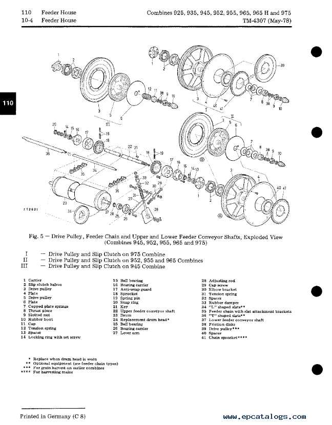
The intricate design and arrangement of components within a robust agricultural machine play a critical role in its overall performance. These components work in harmony to ensure smooth operation, making maintenance and replacement essential for long-term reliability. By gaining a deeper insight into how these elements fit together, you can keep your equipment in excellent condition.
Exploring the detailed layout of key mechanisms allows operators and technicians to address potential issues effectively. Knowing where each component belongs and how it interacts with the rest of the system provides a foundation for efficient troubleshooting and maintenance practices.
Whether you’re performing routine upkeep or making necessary repairs, understanding the complete layout of the internal mechanisms can make all the difference. Familiarizing yourself with this detailed configuration is an invaluable step in ensuring the long-lasting functionality of your machine.
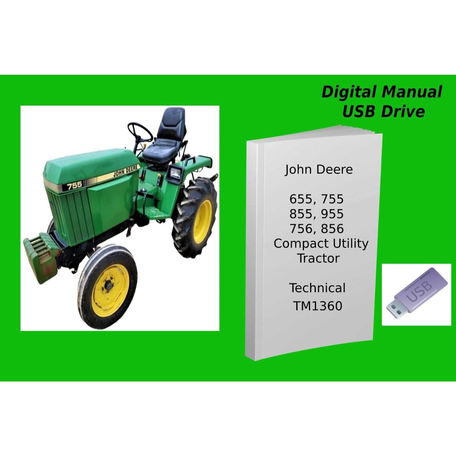
Overview of John Deere 955 Components
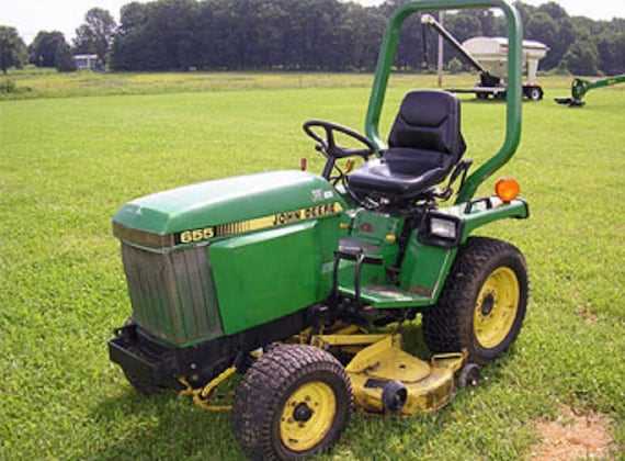
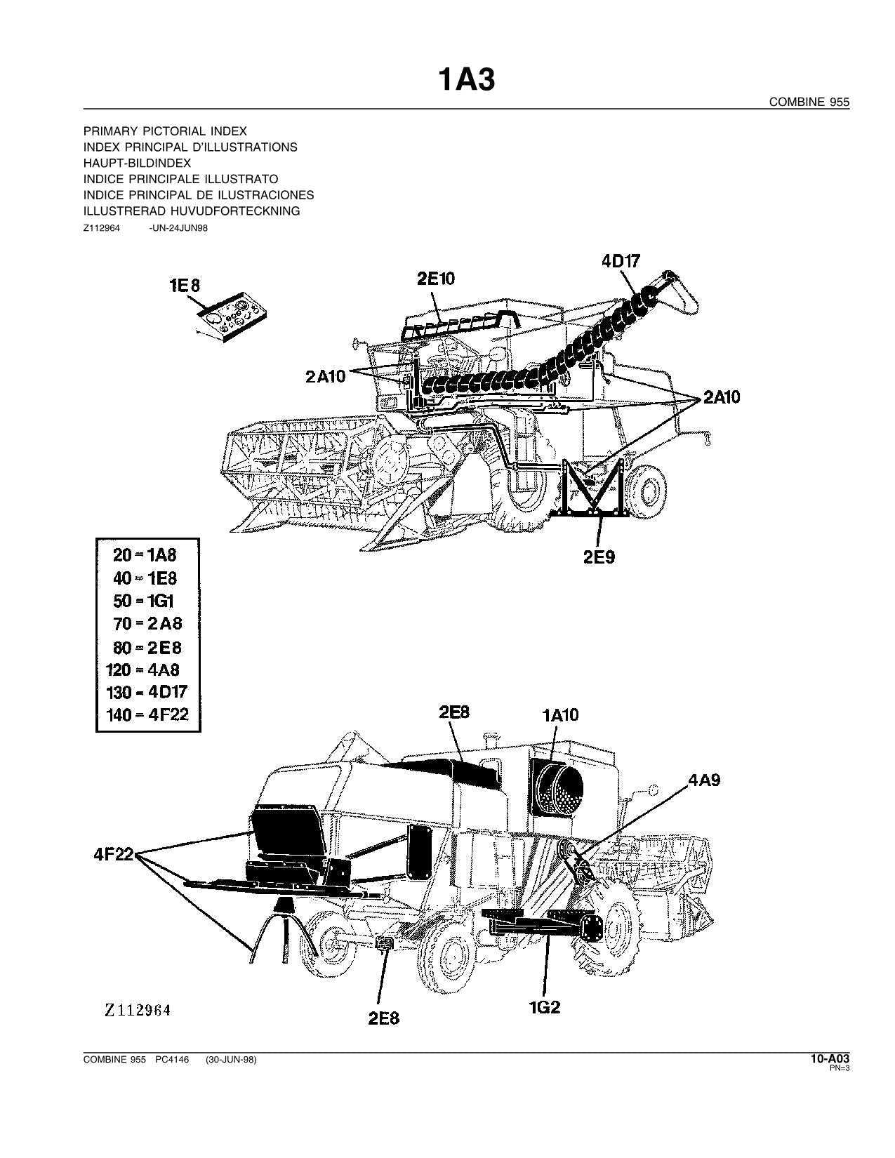
The mechanical structure of this versatile machine consists of numerous interconnected elements, each playing a vital role in its overall functionality. These units are meticulously designed to work in harmony, ensuring smooth operation and reliable performance across various tasks.
Key Functional Elements
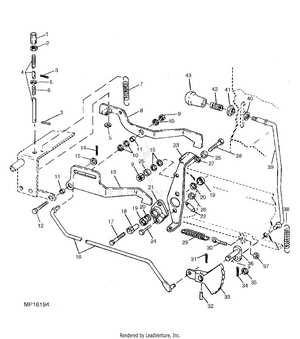
At the core of the system are components responsible for propulsion, control, and power distribution. These include engines, transmission units, and hydraulic systems, all working together to provide the necessary force and precision during operation. Each element is built for durability, aiming to withstand challenging working environments.
Supporting Systems
In addition to the primary mechanisms, there are auxiliary systems that ensure optimal performance. Cooling systems, filtration units, and electrical wiring contribute to maintaining the machine’s efficiency. Proper maintenance of these parts is essential for extending the operational lifespan of the entire system.
Understanding the Hydraulic System Layout
The hydraulic system is a key component in ensuring efficient operation, as it powers various essential functions. To fully grasp how the system works, it’s important to explore its structure and flow. The system is made up of several interconnected elements that work together to generate and distribute power, allowing the machine to perform its tasks smoothly and efficiently.
| Component | Function |
|---|---|
| Pump | Generates the necessary pressure for fluid movement. |
| Hydraulic Lines | Transmit fluid between various parts of the system. |
| Valves | Control the direction and flow rate of the fluid. |
| Cylinders | Convert fluid pressure into mechanical force. |
By understanding the arrangement and purpose of each part, you can ensure optimal maintenance and troubleshooting, keeping the system running
Exploring the Electrical Wiring Diagram
The electrical system of any machinery is a complex network, designed to ensure all components work seamlessly. Understanding this wiring structure is crucial for effective maintenance and troubleshooting. This section delves into the key elements of the electrical schematic, offering insight into how power flows through the system.
Main Components of the Wiring Layout
- Power Source: The initial point where electrical energy is generated or stored, ensuring the system’s functionality.
- Conductors: Wires and cables that transmit electrical current to various sections of the equipment.
- Connectors: Critical points where different wires and circuits are joined, allowing the transfer of power or data.
Understanding Circuit Paths
- Primary Circuits: These circuits control major systems, including ignition and lighting, responsible for key operational functions.
- Secondary Circuits: These paths handle additional features, such as sensors or auxiliary controls, ensuring overall efficiency.
Detailed View of Engine Assembly
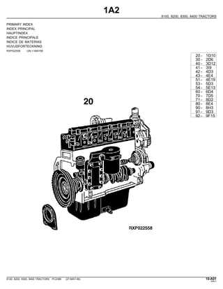
The engine assembly is a critical component, ensuring the proper functioning and performance of the machinery. This section provides a thorough breakdown of the individual elements that come together to form the engine. By understanding the key components and how they interconnect, maintenance and troubleshooting become more manageable, allowing for efficient upkeep.
Component Description Cylinder Block Houses the cylinders and other essential parts such as pistons and crankshaft. Crankshaft Converts the linear motion of pistons into rotational movement to drive the machinery. Pistons Move up and down within Transmission System Breakdown
The transmission system plays a crucial role in ensuring efficient power transfer within any machine. This complex mechanism is responsible for controlling the flow of energy from the engine to the wheels, allowing for smooth operation and optimal performance in a variety of conditions.
Main Components
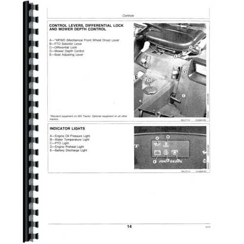
At the core of the system are several essential components, including gears, clutches, and shafts. Each part works in unison to adjust the speed and torque, providing flexibility in operation. Gears handle the changes in speed, while clutches manage the engagement and disengagement between different parts of the mechanism.
Functionality and Adjustments
The system’s ability to adapt to different working environments makes it highly efficient. By modulating gear ratios, the transmission allows for both high-speed travel and low-speed precision tasks, offering a versatile range of operations that can be adjusted depending on the needs of the machine.
Insight into Steering Mechanism Parts
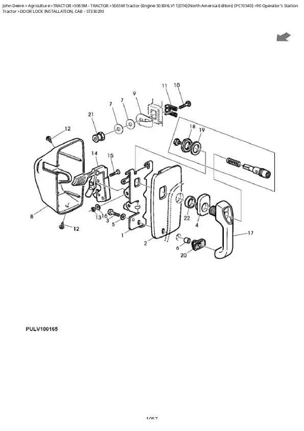
The steering mechanism is crucial for ensuring precise navigation and control of machinery. This section delves into the various components that contribute to its functionality, emphasizing their roles and interactions within the system.
Understanding the elements that make up the steering mechanism can enhance maintenance efforts and improve overall performance. Key components include:
- Steering Wheel: The primary interface for operators to guide the machine.
- Steering Column: Connects the steering wheel to the gearbox, allowing for efficient transfer of motion.
- Gearbox: Converts the rotational movement from the steering wheel into lateral movement of the wheels.
- Linkage System: Connects the gearbox to the wheels, facilitating smooth directional changes.
- Ball Joints: Allow for flexibility and adjustment within the linkage system, ensuring responsive steering.
Each of these components plays a vital role in achieving a seamless steering experience. Regular inspection and maintenance of these parts are essential to prevent wear and ensure the longevity of the steering mechanism.
Identifying Key Cooling System Components
The cooling system in agricultural machinery plays a crucial role in maintaining optimal operating temperatures, thereby ensuring efficiency and longevity. Understanding the essential elements of this system is vital for proper maintenance and troubleshooting. By familiarizing oneself with the main components, operators can effectively manage temperature regulation and prevent overheating.
At the heart of the cooling system lies the radiator, responsible for dissipating heat generated by the engine. This component works in tandem with the water pump, which circulates coolant throughout the system. Additionally, the thermostat regulates coolant flow based on temperature, allowing for efficient heat management. The presence of hoses and connections facilitates the movement of the coolant, ensuring a seamless operation.
Monitoring the coolant reservoir is also critical, as it provides a visual indication of fluid levels and potential leaks. Regular inspection of these components can prevent costly repairs and extend the lifespan of the machinery. Understanding the function and interaction of these key elements will enhance overall performance and reliability.
Attachment Options and Mounting Points
When it comes to enhancing the functionality of agricultural machinery, understanding the various accessory configurations and their corresponding installation locations is essential. This knowledge allows operators to customize their equipment according to specific tasks, improving efficiency and effectiveness in the field.
Different implements can be attached to machinery, providing versatility for diverse agricultural applications. Each attachment option has designated mounting points that ensure secure and stable connections. Below is a summary of common accessories along with their respective installation points:
Accessory Type Installation Location Plow Rear Mounting Bracket Harrow Side Mounting Points Seeder Front Attachment Plate Baler Rear Hitch Connection Sprayer Mid-Mount Brackets By exploring these configurations, operators can optimize their machinery for specific tasks, leading to increased productivity and improved performance across various agricultural processes.
Common Parts Replacement Guide
This section aims to assist users in understanding the various components of their machinery that may require periodic substitution. Recognizing and replacing essential elements is crucial for maintaining optimal functionality and prolonging the lifespan of equipment.
Below are some frequently replaced components:
- Belts
- Filters
- Batteries
- Hoses
- Sensors
When planning a replacement, consider the following steps:
- Identify the component that needs to be changed.
- Consult the maintenance manual for specific instructions.
- Gather the necessary tools and new components.
- Carefully follow the removal and installation guidelines.
- Test the machinery to ensure proper operation after the replacement.
By adhering to these recommendations, users can effectively manage the upkeep of their equipment and enhance its performance.