In the world of heavy equipment, the precise configuration of various mechanisms plays a pivotal role in ensuring efficient performance. Farmers and machinery operators rely on an in-depth knowledge of how key elements of their machines fit together. This knowledge allows for timely maintenance, repairs, and the replacement of worn-out items, which helps to extend the lifespan of valuable equipment.
Accurate visualization of component layouts is essential for anyone working with agricultural equipment. It provides a clear guide on where each element is positioned and how it interacts with others. Whether addressing issues related to the hydraulic system or the engine assembly, having a detailed view of all elements is indispensable.
With a well-organized overview, operators can quickly locate specific areas requiring attention, helping to avoid downtime. Keeping a reference guide for these configurations ensures that troubleshooting and adjustments are carried out smoothly and efficiently.
Understanding the Key Components of the John Deere 335

The proper functioning of any mechanical system relies on the seamless collaboration of its essential elements. This section will explore the primary structures that ensure optimal operation and performance, providing a closer look at the various units and mechanisms involved.
Engine and Powertrain
The core of any equipment lies in its engine, which supplies the necessary force to drive all operations. In this case, the powertrain works in harmony with the motor to deliver efficient performance while maintaining smooth transitions during movement. Key elements to consider include:
- Engine block for efficient power generation
- Transmission system ensuring fluid power distribution
- Cooling mechanisms preventing overheating during operation
Steering and Control Systems
Precise control is essential for maneuverability and safety. The guidance mechanisms, along with the control systems, allow the operator to easily manage direction and speed. Main features include
Engine and Powertrain Overview

The system that drives a machine’s performance is based on a combination of critical components. Understanding how the central unit and its associated mechanisms work together is key to ensuring efficiency and reliability in operation. This section provides an in-depth look at the core driving force and how different elements interact to deliver optimal power output.
Power Generation: At the heart of every machine lies its source of power, which transforms energy into mechanical motion. The proper maintenance and alignment of this core element are essential for smooth and uninterrupted operation.
Power Distribution: Once generated, the energy must be efficiently distributed through various connected components. Each part plays a role in ensuring that the generated force is transmitted with minimal loss, making sure that the entire system operates cohesively.
Electrical System Layout and Connections
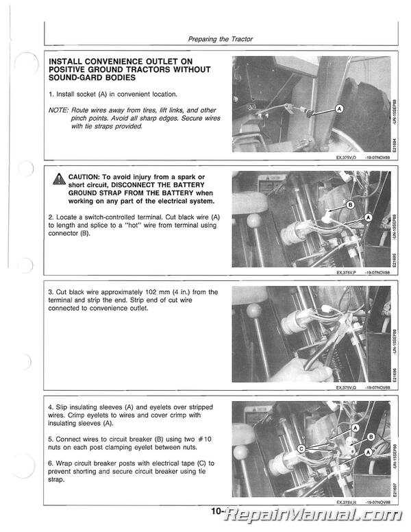
The electrical configuration of any equipment is essential for its proper functionality. Understanding the key elements and how they are interconnected helps ensure safe operation and efficient maintenance. This section will provide an overview of how the different components are linked together within the system, offering insights into their roles and connections.
Below is a representation of the basic structure of the electrical wiring and connections that maintain the smooth operation of the system:
| Component | Description | Connection Point | |||||||||||||||||||||||||||||||||||||||||||||
|---|---|---|---|---|---|---|---|---|---|---|---|---|---|---|---|---|---|---|---|---|---|---|---|---|---|---|---|---|---|---|---|---|---|---|---|---|---|---|---|---|---|---|---|---|---|---|---|
| Battery | Supplies power to the entire electrical system, enabling startup and operation. | Main power junction | |||||||||||||||||||||||||||||||||||||||||||||
| Starter | Activates the engine by receiving electrical current from the battery. | Connected via ignition switch | |||||||||||||||||||||||||||||||||||||||||||||
| Alternator | Recharges the battery and powers electrical accessories when the engine is running. | Attached to power distribution system
Hydraulic Parts and FunctionsHydraulic systems are essential for various machinery, enabling efficient movement and power transmission through pressurized fluid. These systems consist of several interconnected components, each playing a critical role in controlling and directing the flow of fluid to achieve specific mechanical tasks. Understanding the main elements of these systems can help maintain optimal performance and reliability in complex operations. Pumps are the heart of the system, responsible for converting mechanical energy into hydraulic power by moving fluid through the system. Without a functioning pump, the entire mechanism would fail to operate effectively. Cylinders serve as actuators that convert the hydraulic pressure into mechanical force, driving movement in various machine parts. These components are crucial for lifting, pushing, and pulling operations, ensuring smooth and controlled motions. Valves Blade Assembly and Maintenance GuideEnsuring the proper setup and upkeep of the cutting components is essential for efficient and safe operation. The assembly process requires attention to detail, as the alignment and connection of each part directly impact performance. Regular maintenance not only extends the lifespan of the equipment but also helps maintain optimal cutting quality. Steps for Assembling the Cutting MechanismBegin by securing the primary components in place, following the manufacturer’s instructions. Properly align the cutting edges and fasten them with appropriate hardware, ensuring all connections are tight but not over-torqued. Misalignment or loose connections can lead to performance issues or uneven cuts.
|
