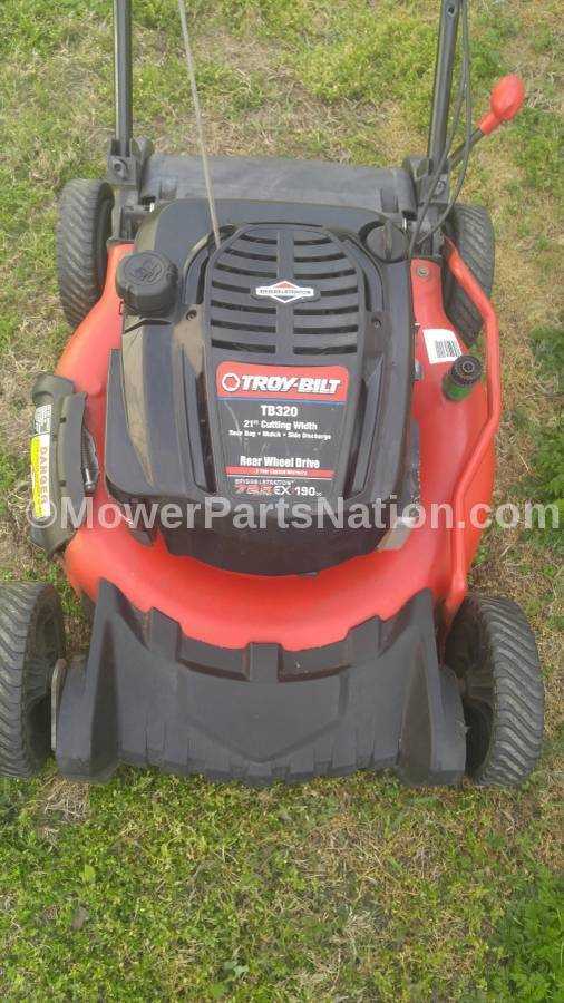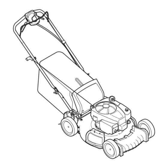
A well-maintained lawn mower is essential for keeping your yard in pristine condition. Each machine is composed of various critical elements that ensure its functionality and durability. Understanding these elements is key to keeping your equipment in top shape and extending its lifespan.
Every component within this equipment plays a specific role, contributing to its overall efficiency and ease of operation. From the engine to the cutting mechanisms, each piece is designed with precision to work together seamlessly. Familiarizing yourself with these elements can make routine upkeep and necessary repairs more manageable.
In this guide, we will explore the key sections of this machine, helping you recognize and identify crucial features. Whether you’re looking to troubleshoot an issue or simply want to enhance your understanding, this information will offer clarity and support in maintaining your equipment effectively.
Exploring the Structure of the TB320 Mower
The design of this lawn mower emphasizes efficiency and durability, offering users a reliable solution for maintaining their outdoor spaces. Its assembly combines various components that work seamlessly to ensure smooth operation. Understanding the layout and functionality of each element can enhance the overall performance of the machine, making maintenance tasks easier and more effective.
The framework supports essential mechanisms that allow precise cutting, effortless propulsion, and easy handling. Key features include the engine’s placement, the drive system, and the cutting mechanism, all integrated into a cohesive unit that maximizes efficiency. Examining these structural elements will give a clearer insight into how this mower operates and what makes it a valuable tool for lawn care.
Key Components of the Troy-Bilt TB320
The machine is designed with several crucial elements that work in unison to deliver effective and efficient performance. Each part is carefully constructed to fulfill a specific function, ensuring a balanced operation. This section outlines the main elements that contribute to its reliability and usability.
Engine and Drive System
The heart of the unit lies in its power source, which provides the necessary force to handle various tasks. Coupled with a dependable drive mechanism, these two components ensure smooth movement and steady power distribution, enhancing overall operational effectiveness.
Cutting System and Blade Assembly
The cutting feature, equipped with a sharp and durable blade assembly, plays a pivotal role in achieving precise and even results. Designed for resilience, the blade system allows for continuous use without compromising performance, contributing significantly to its long-term functionality.
Blade Assembly and Its Role
The cutting mechanism is a key component in any machine designed for maintaining a healthy lawn. The blades serve not only to trim vegetation but also to enhance the overall performance of the equipment by ensuring an even cut. Proper installation and upkeep of this mechanism is essential for optimal functioning and a smooth cutting experience.
Components of the Cutting Mechanism
The cutting system consists of several interconnected elements. Each part plays a crucial role in ensuring that the mechanism works efficiently. Understanding these components helps in maintaining the assembly and addressing any potential issues before they affect performance.
| Component | Function | ||||||||||||||||||||||||||||||||||||
|---|---|---|---|---|---|---|---|---|---|---|---|---|---|---|---|---|---|---|---|---|---|---|---|---|---|---|---|---|---|---|---|---|---|---|---|---|---|
| Cutting Blade | Responsible for trimming grass to the desired height. | ||||||||||||||||||||||||||||||||||||
| Blade Mount | Secures the blade to the rotating
Engine Layout and Functionality OverviewThe structure of the motor system plays a critical role in ensuring efficient operation and performance. By understanding the basic arrangement and how each element interacts, users can appreciate the significance of every component and its contribution to the overall function. This section provides a breakdown of the key segments and highlights their primary roles in powering the machine. Main Sections of the Engine
How the Components Work Together
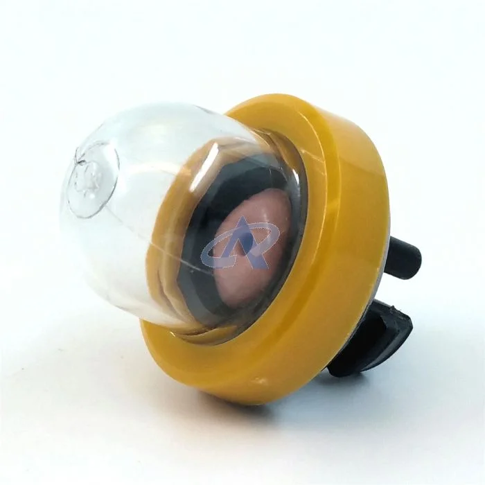
Understanding the Drive SystemThe propulsion mechanism plays a crucial role in ensuring smooth and efficient operation of a machine. It is responsible for transferring power from the engine to the wheels, allowing the equipment to move forward and backward with ease. A well-functioning drive setup ensures that the device maintains steady speed control, optimal maneuverability, and handles various terrains effectively. The system typically consists of several key components that work together to deliver reliable performance. These include the transmission, belts, pulleys, and axles, each contributing to the overall motion. Proper maintenance of these elements is essential to prevent breakdowns and prolong the lifespan of the equipment. When examining how this mechanism functions, it’s important to understand the relationship between the power source and the wheel assembly. Regular inspection and timely replacement of worn-out parts can significantly enhance the operational efficiency and ensure long-term reliability. Fuel System Parts and Their FunctionThe fuel system in outdoor power equipment plays a crucial role in ensuring efficient engine performance. This system is responsible for storing, filtering, and delivering fuel to the engine, allowing for smooth operation. Understanding the components of this system and their specific functions is essential for maintenance and troubleshooting.
Handlebar and Control Mechanisms BreakdownThe handlebar assembly is a crucial component that significantly influences the user experience and functionality of outdoor power equipment. Understanding the various elements and their interconnections is essential for effective operation and maintenance. This section delves into the key components that make up the handlebar system and the control mechanisms that facilitate smooth and precise handling. Key Components of the Handlebar AssemblyThe handlebar assembly consists of several integral parts that work together to ensure efficient operation. Each component serves a specific purpose, contributing to the overall performance and usability of the machinery. The main components include:
Understanding Control Mechanisms
Control mechanisms are vital for managing the performance and functionality of outdoor equipment. These systems allow the operator to adjust settings and ensure optimal operation. Key control elements include:
Maintenance Tips for Key TB320 PartsRegular upkeep of essential components in your outdoor equipment can significantly enhance its performance and lifespan. Proper care not only ensures optimal functionality but also prevents potential breakdowns that could lead to costly repairs. Implementing a routine maintenance schedule can help you identify issues early and keep your machinery running smoothly. Engine Care
The heart of any machine, the engine, requires special attention. Ensure that you regularly check the oil level and quality, replacing it according to the manufacturer’s recommendations. Clean or replace air filters to maintain airflow and efficiency. Additionally, inspect spark plugs for wear and replace them if necessary to ensure reliable starting and operation. Fuel System MaintenanceA well-maintained fuel system is crucial for optimal performance. Regularly inspect fuel lines for cracks or leaks, as these can lead to inefficient operation or safety hazards. Use high-quality fuel and consider adding a fuel stabilizer to prevent degradation, especially if the equipment will be idle for extended periods. Regularly cleaning the carburetor will also help maintain smooth operation. How to Identify Worn-Out Components
Recognizing the signs of deterioration in mechanical devices is crucial for maintaining optimal performance and ensuring longevity. Components that exhibit wear can lead to inefficiencies, increased energy consumption, and potential failures if not addressed promptly. Here are some common indicators to help identify these parts before they affect the overall functionality. Visual Inspection
Conducting a thorough visual examination can reveal much about the condition of various elements. Look for:
Performance Indicators
Monitoring the performance of equipment can also provide insights into potential wear:
By paying close attention to both visual cues and performance metrics, users can effectively identify worn-out parts and take appropriate action to maintain their equipment in peak condition. |
