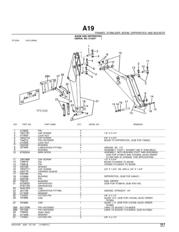
The intricate workings of heavy machinery rely on a myriad of essential elements that ensure optimal performance. Each component plays a pivotal role in the overall functionality, making it crucial for operators and mechanics to grasp their interconnections.
When exploring the layout of these components, one can gain invaluable insights into the maintenance and repair processes. A clear representation of these parts facilitates a deeper understanding, empowering users to troubleshoot and optimize their equipment effectively.
In this discussion, we will delve into the various segments of a specific piece of construction equipment, examining their ultimate functions and relationships. By familiarizing oneself with these structures, operators can enhance both efficiency and longevity in their machinery’s operation.
Understanding the John Deere 310A
This section explores the essential components and features of a popular piece of construction equipment. Known for its durability and versatility, this machine is designed to tackle a variety of tasks efficiently. By examining its structure and functions, users can better appreciate its capabilities and maintenance needs.
Key Features and Capabilities
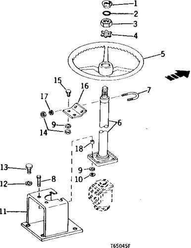
The equipment boasts a robust engine that provides significant power for heavy-duty operations. Its hydraulic system enhances performance, allowing for smooth operation of attachments. Users often find that its compact design makes it suitable for both tight spaces and larger job sites, offering flexibility in various conditions.
Maintenance and Care
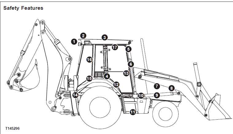
Regular upkeep is crucial to ensure optimal performance. Familiarity with the machine’s components allows operators to identify wear and tear early, preventing costly repairs. Proper lubrication and timely inspections are vital practices that can prolong the life of this reliable equipment.
Components of the Backhoe Loader
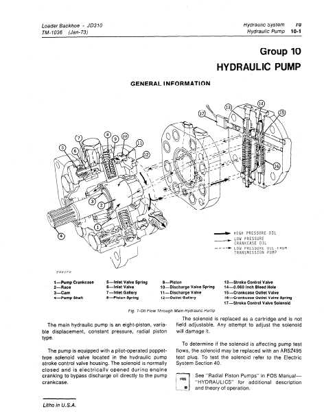
The versatility of an excavator-loader stems from its array of integral elements, each designed to enhance functionality and efficiency. Understanding these components is crucial for optimizing performance and ensuring seamless operation in various tasks.
1. Loader Bucket: This front attachment is primarily used for lifting and moving materials. Its design can vary based on the specific requirements, including capacities for digging, hauling, and leveling.
2. Digger Arm: This crucial element allows for deep excavation and precise maneuvering. The arm’s hydraulic system enables it to reach significant depths, making it ideal for trenching and foundational work.
3. Hydraulic System: The hydraulic mechanism is the powerhouse of the equipment, providing the necessary force for lifting and digging. It converts fluid pressure into mechanical energy, allowing for smooth operation of all attachments.
4. Stabilizers: These are vital for maintaining balance and preventing tipping during operation. Properly deployed, they enhance stability when digging or lifting heavy loads.
5. Chassis: The framework serves as the foundation of the machine, supporting all other components. Its robust construction ensures durability and resilience under tough working conditions.
6. Tires: Designed for mobility and traction, the tires play an essential role in maneuvering across diverse terrains. Their tread patterns and sizes can be optimized for specific operational environments.
7. Control System: The operator’s interface allows for precise manipulation of the machine’s functions. Ergonomic designs and intuitive layouts facilitate ease of use, enhancing overall productivity.
Each of these components plays a significant role in the overall performance of the loader-excavator, contributing to its reputation as a reliable workhorse in construction and excavation tasks.
Importance of Accurate Parts Diagrams
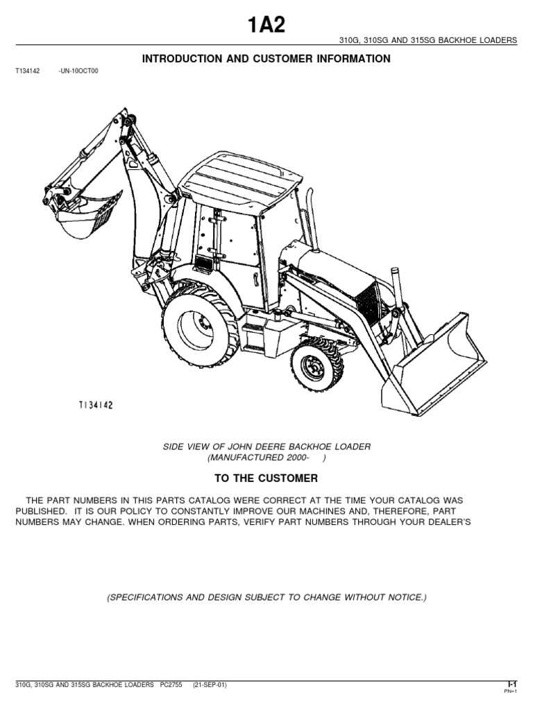
Having precise illustrations of components is crucial for efficient maintenance and repair processes. These visual aids serve as essential tools, helping users identify each element and its respective function within the machinery. An accurate representation not only facilitates quick troubleshooting but also enhances overall operational efficiency.
Benefits of Detailed Illustrations
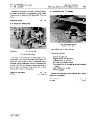
- Improved Efficiency: Clear visuals allow technicians to locate and address issues swiftly, reducing downtime.
- Enhanced Understanding: Comprehensive images provide a better grasp of complex systems, making it easier for users to learn and apply their knowledge.
- Reduced Errors: Precise diagrams minimize the risk of misidentification, leading to fewer mistakes during repairs or replacements.
Essential for Ordering Components
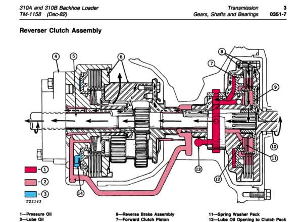
- Accurate Identification: Clear depictions help ensure that the correct items are ordered, avoiding delays caused by receiving the wrong parts.
- Streamlined Procurement: Visual references can speed up the ordering process by allowing suppliers to understand exactly what is needed.
- Cost Efficiency: Reducing errors in ordering directly contributes to saving time and money in repair operations.
Common Issues with 310A Parts
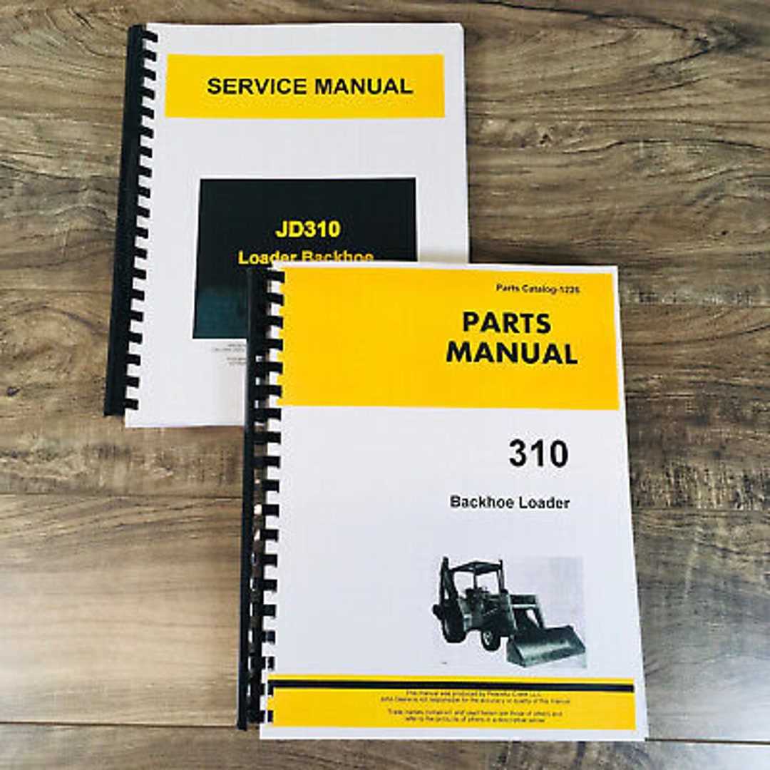
Understanding the frequent challenges associated with specific machinery components can greatly enhance maintenance and repair processes. Over time, certain elements may exhibit wear or malfunction, leading to operational inefficiencies. Identifying these common issues helps ensure longevity and reliability of the equipment.
Frequent Problems
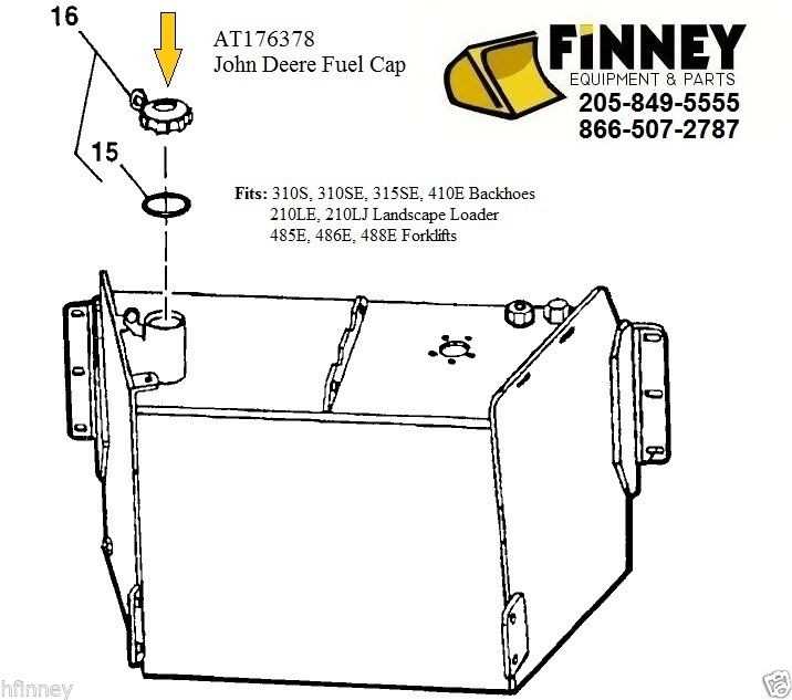
- Hydraulic leaks: Seals and hoses can degrade, causing fluid loss and reduced performance.
- Electrical failures: Wiring and connections may corrode or become loose, leading to intermittent power issues.
- Engine overheating: Cooling systems might be compromised, resulting in excessive heat and potential engine damage.
Prevention Strategies
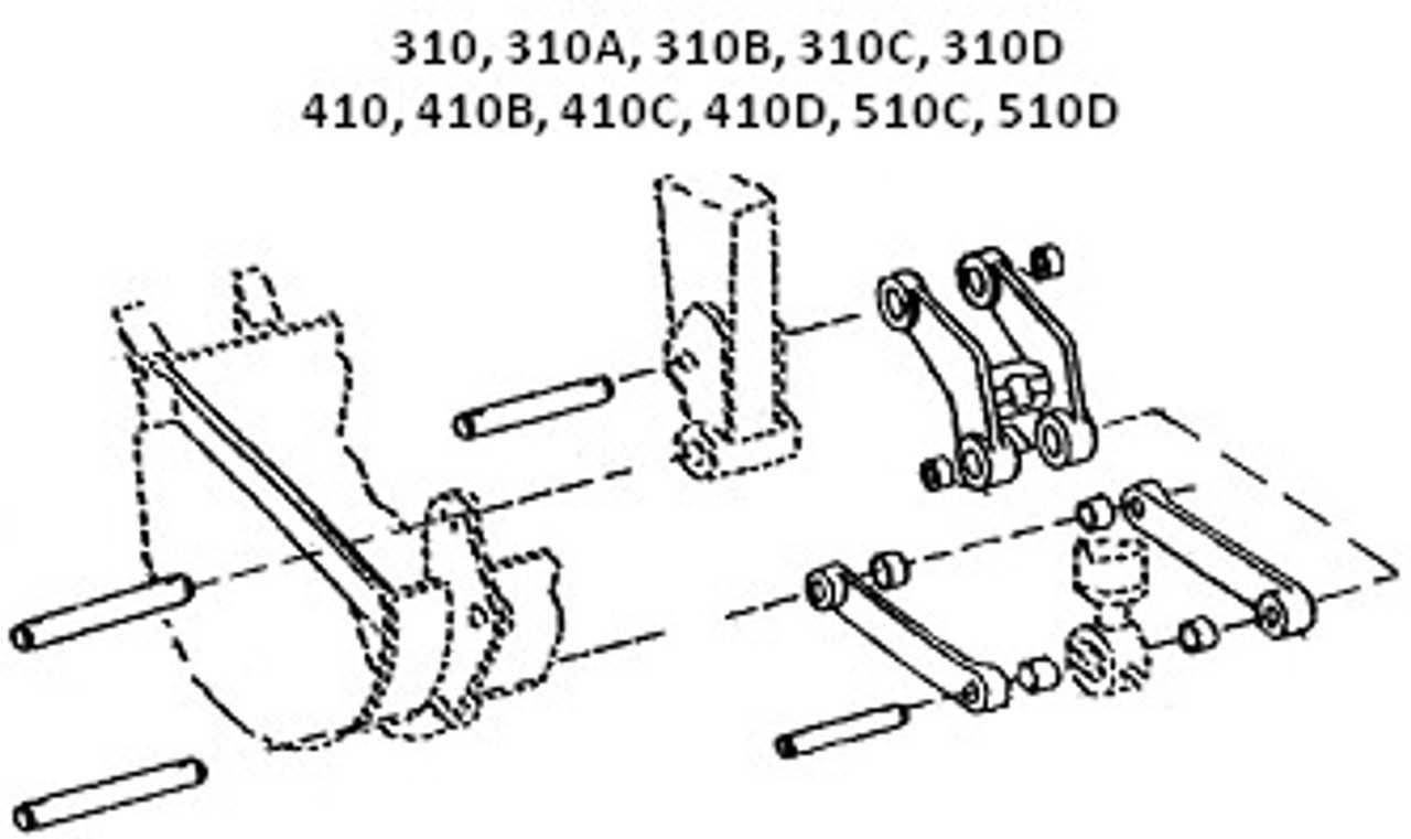
- Regular inspections: Schedule routine checks to identify wear and address issues promptly.
- Use quality fluids: Ensure that hydraulic and engine fluids meet manufacturer specifications to prevent breakdowns.
- Follow maintenance guidelines: Adhere to recommended service intervals for optimal performance.
How to Access Parts Diagrams
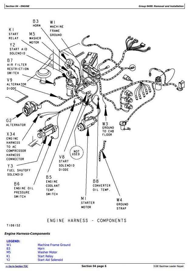
Understanding the layout and components of machinery is essential for effective maintenance and repair. Accessing visual representations of these elements can significantly enhance your ability to identify and replace necessary components. This section provides guidance on locating and utilizing these valuable resources.
To begin, many manufacturers offer online resources where you can find detailed illustrations and schematics. These can typically be accessed through the official website or dedicated customer support portals. By entering the model information, users can often retrieve the needed visual aids quickly.
Additionally, consulting service manuals is another effective method. These manuals not only contain visual references but also include vital information about each part’s specifications and functions. Local dealerships or authorized service centers may also have physical copies available for purchase or reference.
Furthermore, engaging with online communities and forums can provide access to shared diagrams and user-generated content. Fellow enthusiasts often upload their own materials, creating a wealth of information that can aid in your repair efforts.
In summary, accessing visual references for machinery components is straightforward when utilizing manufacturer resources, service manuals, and community forums. These tools empower users to carry out repairs with confidence and accuracy.
Replacement Parts for the 310A
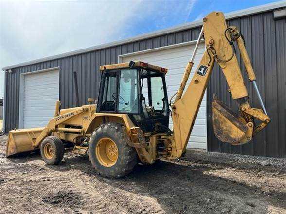
Maintaining the efficiency of heavy machinery often requires sourcing new components to replace worn or damaged items. Ensuring that your equipment operates smoothly is essential for both performance and longevity. This section highlights the critical components you may need to consider when repairing or upgrading your machinery.
Essential Components Overview
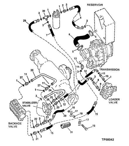
When dealing with any machinery, understanding the key elements that contribute to its operation is vital. This includes a range of items from hydraulic systems to structural elements, all of which play a role in the overall functionality.
Replacement Components Table
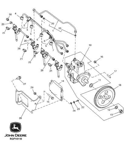
| Component | Description | Importance |
|---|---|---|
| Hydraulic Cylinder | Transmits fluid pressure to create movement. | Crucial for lifting and digging functions. |
| Bucket | Primary tool for excavation and material handling. | Directly impacts efficiency and capability. |
| Transmission | Transfers power from the engine to the wheels. | Essential for mobility and operational control. |
| Filters | Removes contaminants from fluids. | Protects engine and hydraulic systems from damage. |
Identifying the right replacements and ensuring their quality is key to maintaining optimal performance. Proper selection not only enhances functionality but also extends the life of the equipment.
Tips for Maintenance and Repair
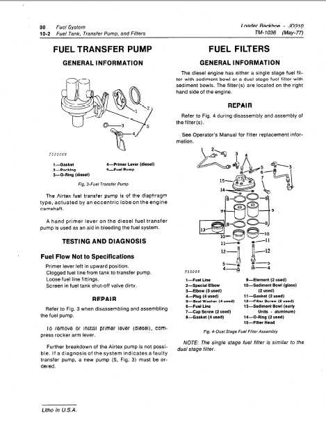
Proper upkeep and timely repairs are essential for the longevity and efficiency of heavy machinery. Regular attention not only prevents major breakdowns but also enhances overall performance. Here are some key suggestions to ensure your equipment remains in optimal condition.
- Regular Inspections: Conduct frequent checks on all components. Look for signs of wear and tear, leaks, or unusual noises.
- Fluid Levels: Maintain appropriate fluid levels, including hydraulic fluid, engine oil, and coolant. Low levels can lead to overheating and damage.
- Clean Filters: Regularly clean or replace air, fuel, and hydraulic filters to ensure efficient operation.
In addition to routine maintenance, addressing issues promptly can prevent minor problems from escalating.
- Document Repairs: Keep a detailed log of all maintenance activities and repairs. This helps track the history and can inform future servicing.
- Use Genuine Parts: When replacements are necessary, opt for original components to ensure compatibility and reliability.
- Follow Manufacturer Guidelines: Always refer to the manufacturer’s manual for specific maintenance schedules and procedures.
By adhering to these maintenance and repair strategies, you can significantly enhance the durability and performance of your machinery.
Where to Buy Genuine Parts
Finding authentic components for your machinery is essential to ensure optimal performance and longevity. Many sources offer reliable options, but it’s crucial to choose suppliers known for their quality and service.
| Source | Description |
|---|---|
| Authorized Dealers | These retailers provide certified products and expert advice, ensuring compatibility and quality. |
| Manufacturer’s Website | Direct online purchasing can be convenient, offering a comprehensive range of original items. |
| Specialized Retailers | Stores focused on machinery often have a wide selection of genuine components and knowledgeable staff. |
| Online Marketplaces | Reputable platforms can connect you with trusted sellers, but verify authenticity before purchasing. |