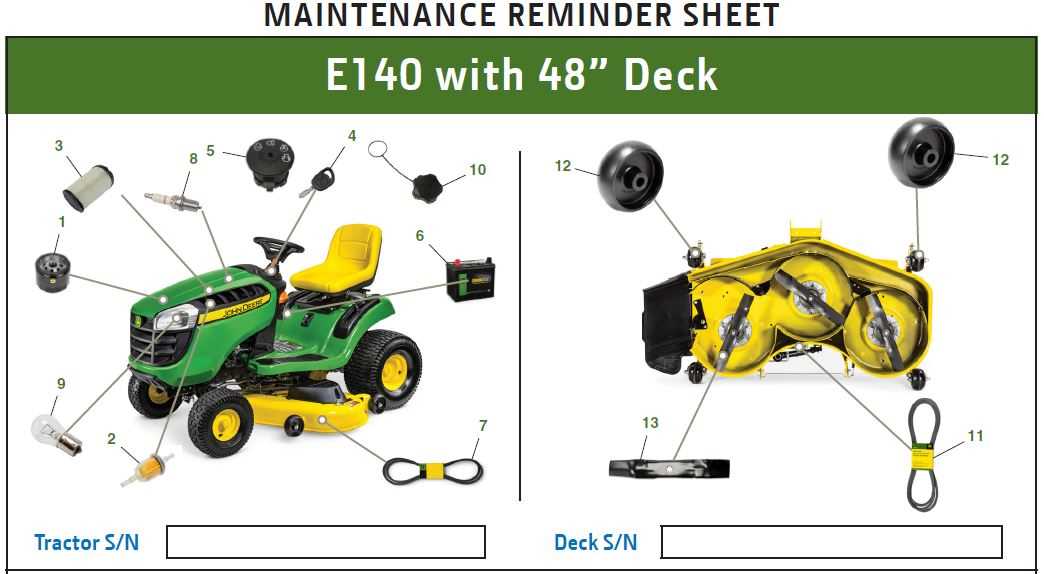
For any machine to operate efficiently, each element within its structure plays a crucial role. The seamless interaction between these components ensures reliable functionality, whether for daily tasks or more demanding activities. By focusing on individual elements, you can achieve better overall performance and longevity.
Identifying and understanding how these critical mechanisms work together can make maintenance and repairs easier. From simple replacements to more complex adjustments, knowing the structure and function of each piece will help maintain peak efficiency and prevent downtime.
Detailed information on the key mechanisms is essential for anyone looking to extend the lifespan of their equipment. A thorough understanding of these elements not only simplifies upkeep but also enhances the operational quality of the machine.
Comprehensive Overview of the E140 Structure
Understanding the core framework of this machine involves examining its key components and how they work together to achieve optimal performance. By exploring the structure, you gain insights into the mechanical relationships between different sections and their role in maintaining efficiency.
Main Functional Areas
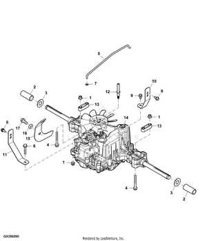
The structure is divided into several main areas, each serving a critical function. These areas ensure smooth operation and provide essential support to the overall mechanism.
- Engine System: Powers the machinery and drives its functions with precision.
- Transmission: Ensures the efficient transfer of energy to the operational components.
- Cutting Mechanism: Provides precision for specific tasks, maintaining a high standard of output.
Additional Components
Beyond the primary systems, several additional elements contribute to the machine’s durability and ease of maintenance.
- Hydraulic Controls: Allow for smooth adjustments and easy control over operations.
- Chassis Framework: Provides the necessary support and stability during heavy usage.
- Safety Features: Integrated to ensure operator protection and
Main Components and Their Functions
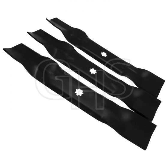
Understanding the key elements and their purposes is essential for ensuring efficient performance and long-term durability. Each system plays a unique role, contributing to the overall functionality of the machinery. Below, we highlight the core mechanisms that allow the equipment to operate smoothly and effectively.
Engine and Power System
The engine serves as the heart of the machine, providing the energy required for all operations. It converts fuel into mechanical energy, driving the unit forward and powering additional systems. Proper maintenance of this power source ensures optimal efficiency and reliability.
Transmission and Drive Mechanism
The transmission is responsible for regulating speed and power distribution. It connects the engine to the wheels or tracks, enabling controlled movement. The drive mechanism ensures that power is efficiently transferred, allowing the machine to navigate different terrains with ease.
Key Diagrams for Engine Parts
Understanding the layout of an engine and its components is crucial for maintenance and repair. Diagrams provide a detailed view of how each element fits within the overall structure, offering valuable insights into the arrangement of key components. This section highlights essential graphical representations that explain the configuration of various mechanical elements found within the engine.
Main Components Overview
The engine consists of numerous interlocking parts that work together to ensure smooth operation. From the pistons and cylinders to the belts and cooling mechanisms, each element plays a pivotal role in the engine’s functionality. A visual guide allows users to easily identify these components and understand their placement within the system.
Mechanical Connections and Functions
Another important aspect of diagrams is their ability to show how different engine components interact. Clear visual guides can demonstrate the flow of power, the function of different belts, and how components like valves and shafts are linked. This level of detail aids in diagnosing issues and making precise adjustments.
Component Function Piston Converts Electrical System and Wiring Breakdown
The electrical system in machinery serves as the backbone for powering various components, ensuring efficient operation and performance. Understanding the layout of the wiring structure is crucial for troubleshooting, maintenance, and optimal functionality. This section provides an overview of how electrical circuits are interconnected, offering insights into key elements that play a pivotal role in the system’s overall performance.
Main Components Overview
The electrical network typically includes several primary elements such as the battery, alternator, fuses, and wiring harness. These components work together to deliver power and protect the machinery from potential electrical faults. Understanding the relationship between these elements is essential for diagnosing issues and performing routine upkeep.
Wiring and Circuit Layout
The wiring layout consists of multiple interconnected circuits that distribute power to different parts of the system. Each circuit has a specific role, whether it’s providing power to the lights, ignition, or control systems. Below is a simplified representation of key circuits within the system:
Circuit Steering and Control Mechanisms
Effective navigation and handling of equipment rely heavily on the systems that control direction and speed. These mechanisms work together to ensure that the operator can steer precisely and maintain control in various conditions. Understanding how the components function is essential for ensuring smooth operation and long-term reliability.
Steering System Components
The steering system is composed of various parts designed to provide responsive movement. This includes the wheel assembly, which transmits the operator’s inputs into turning motion, and the linkages that connect to the primary drive. These elements ensure that the equipment follows the intended path with minimal effort.
Control Mechanisms
The control mechanisms, such as the throttle and brake systems, allow the operator to regulate both speed and stopping power. A combination of levers and pedals makes it possible to accelerate, decelerate, and stop efficiently, providing full control over the movement of the machine. Proper adjustment and maintenance of these controls ensure safe and effective operation.
Transmission and Drive Belt Layout
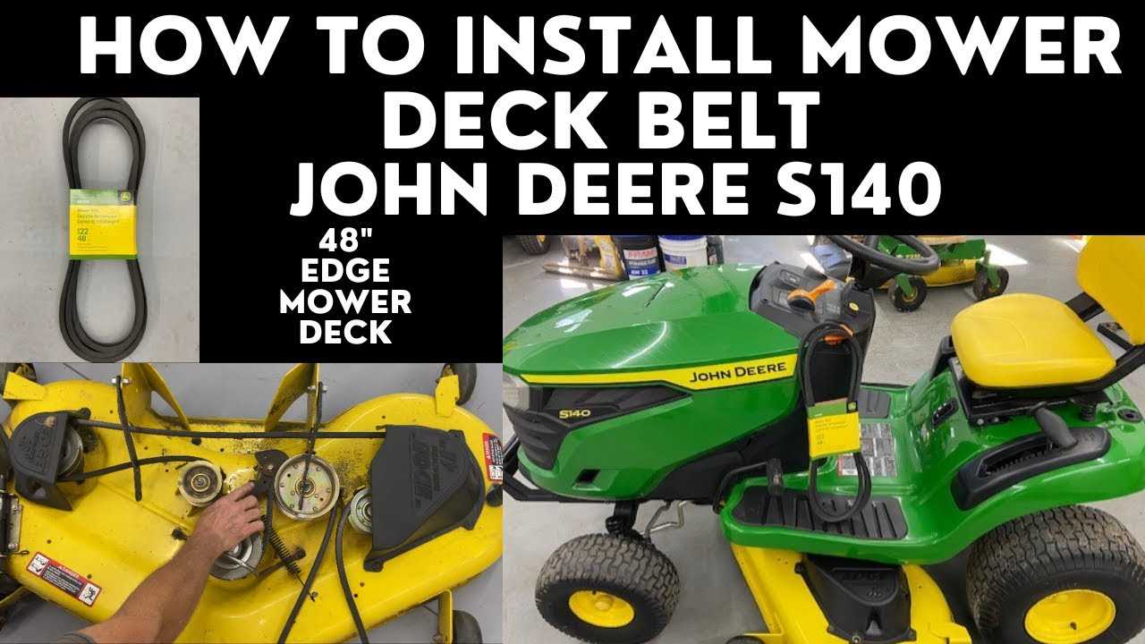
The arrangement of the transmission and drive belt is crucial for the efficient operation of the machinery. This system is responsible for transferring power from the engine to the wheels, enabling smooth movement and optimal performance. Understanding the layout allows for better maintenance and troubleshooting, ensuring longevity and reliability of the equipment.
Components Overview
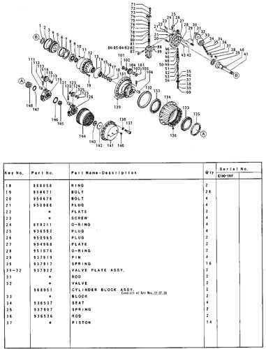
Key elements of this assembly include various belts and pulleys that work in tandem to facilitate motion. The belts are designed to withstand significant stress and wear, making it essential to regularly inspect them for signs of damage or deterioration. Proper alignment of these components is necessary to maintain efficiency and prevent premature failure.
Maintenance Tips
Regular maintenance is vital for the longevity of the transmission system. Inspect belts for signs of wear, such as cracks or fraying, and replace them as necessary. Additionally, ensure that all components are correctly aligned to avoid unnecessary strain on the system. Lubricating moving parts can also enhance performance and reduce friction, contributing to smoother operation.
Chassis and Frame Assembly Details
The chassis and frame assembly serves as the foundational structure for the equipment, providing stability and support for various components. A well-designed assembly ensures that all parts work harmoniously, contributing to the overall performance and longevity of the machine.
Key Components
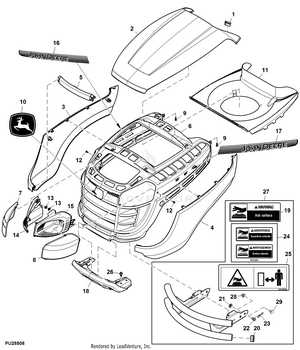
Understanding the essential elements of the chassis and frame assembly is crucial for maintenance and repairs. The following table outlines the primary components involved in this assembly:
Component Description Frame The main structure that supports the entire assembly, ensuring durability and strength. Subframe A secondary structure that reinforces the main frame and helps in distributing weight evenly. Mounting Brackets Connectors that secure various components to the frame, providing stability and alignment. Cross Members Horizontal supports that enhance rigidity and prevent flexing during operation. Assembly Considerations
When assembling or inspecting the chassis and frame, it is vital to ensure that all components are aligned correctly and securely fastened. Regular maintenance checks can prevent issues related to wear and tear, ensuring optimal functionality over time.
Maintenance and Replacement Tips
Regular upkeep and timely substitutions are essential for ensuring optimal functionality and longevity of your equipment. Understanding the necessary procedures can help prevent unexpected breakdowns and enhance overall performance.
When performing maintenance, it is crucial to adhere to the recommended intervals for inspections and replacements. This proactive approach can significantly reduce wear and tear, ultimately extending the lifespan of various components.
Consider the following guidelines to maintain efficiency:
Component Maintenance Tip Replacement Frequency Air Filter Inspect and clean regularly to ensure proper airflow. Every 50 hours of operation Oil Filter Replace during oil changes to maintain engine health. Every 100 hours of operation Blades Sharpen and balance to improve cutting performance. Every 25 hours of operation Battery Check terminals for corrosion and ensure secure connections. Annually By following these recommendations, you can maintain the reliability of your machinery and enhance its efficiency.
Troubleshooting Common Part Issues
Addressing common challenges related to equipment components is essential for maintaining optimal performance. Various issues can arise during operation, leading to inefficiencies or malfunctions. By identifying these problems early, users can implement effective solutions and ensure longevity.
Identifying Symptoms
Recognizing the signs of potential problems is crucial. Symptoms may vary, but some common indicators include unusual noises, reduced functionality, and visible wear. By paying attention to these cues, one can narrow down the potential causes and take corrective measures.
Common Solutions
Once the symptoms have been identified, several strategies can be employed to address the issues. Regular maintenance is key, including inspections and timely replacements of worn-out components. Below is a table outlining some frequent problems and their corresponding solutions:
Issue Potential Solution Noisy operation Check for loose or damaged elements; tighten or replace as necessary. Reduced efficiency Inspect for blockages or dirt accumulation; clean or replace filters. Inconsistent performance Verify proper installation of components; ensure all connections are secure.