Marvel Schebler Carburetor Parts Diagram Overview and Components

marvel schebler carburetor parts diagram

Understanding the inner workings of a mechanical fuel system requires a clear grasp of how its various elements interact. These systems rely on an intricate arrangement of components designed to regulate the flow and mixture of fuel, ensuring optimal performance for different types of engines. This section explores the essential structures and how they fit together, providing a comprehensive look at their individual roles.

The assembly typically involves several critical mechanisms, each playing a vital part in maintaining efficient operation. By examining the layout, one can see how each piece contributes to controlling fuel intake and distribution. This detailed look offers valuable insights for those looking to maintain or repair such systems.

To ensure smooth function, precise tuning and alignment of these elements are necessary. Any misalignment can lead to issues such as poor performance or engine failure. In the following sections, we will delve into the individual components and provide a clearer understanding of their arrangement and function.

Marvel Schebler Carburetor Components Overview

This section provides a detailed breakdown of the key elements that ensure proper functioning and efficiency of classic fuel delivery systems. By understanding the different mechanisms and their purposes, users can maintain and repair their equipment effectively, ensuring smooth and reliable operation over time.

Component Description
Fuel Inlet Responsible for directing fuel into the system, this entry point plays a critical role in managing the flow and ensuring consistent performance.
Float Chamber This section regulates the fuel level by using a float mechanism, maintaining a steady supply of fuel for optimal functioning.
Needle Valve Working alongside the float, this valve controls the amount of fuel that enters the system, helping prevent flooding or fuel starvation.
Main Jet The main

Exploded View of Key Components

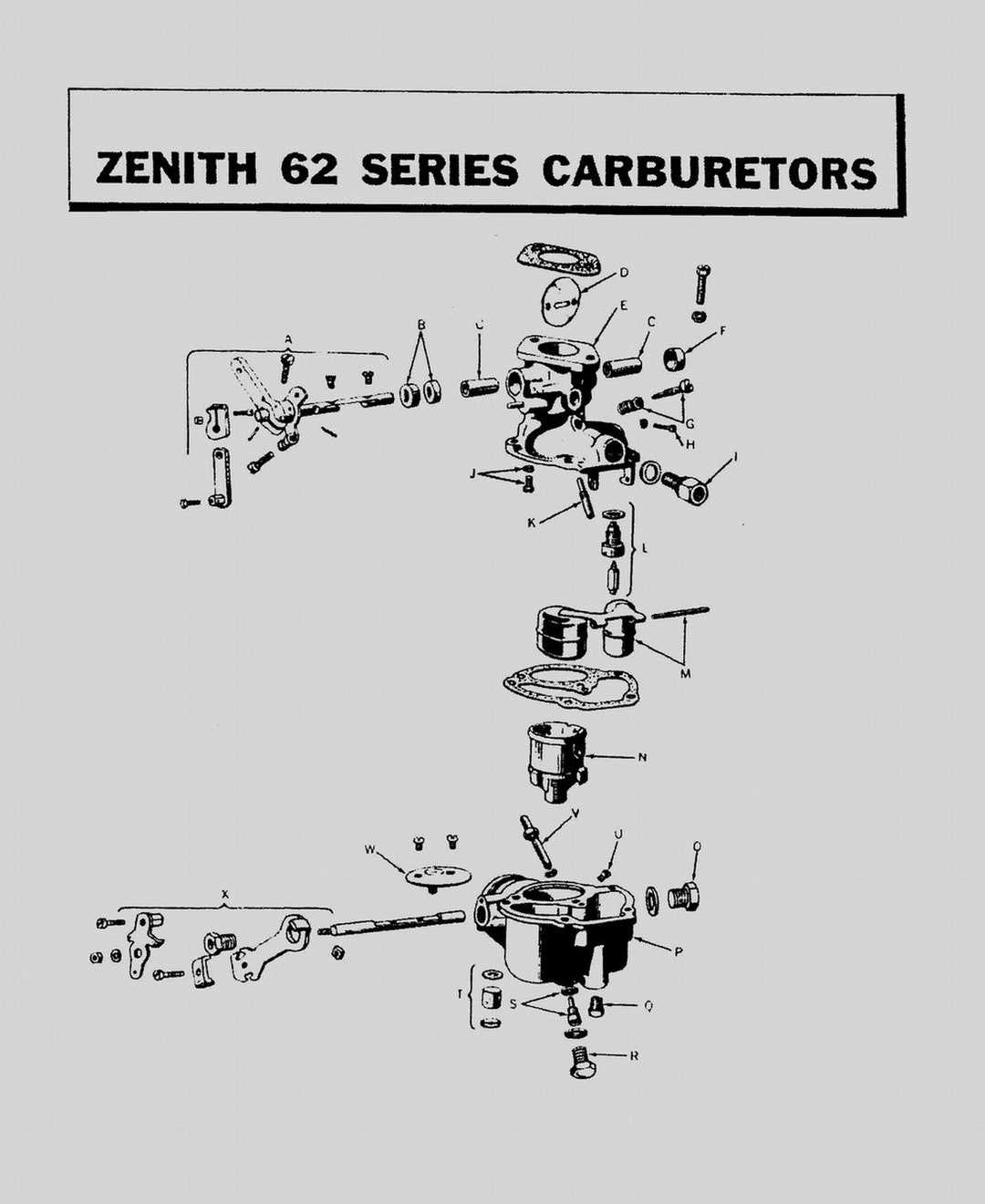
This section provides a detailed visual breakdown of essential elements in the assembly, offering a clear understanding of the structure and arrangement. The exploded view reveals how individual pieces fit together, making it easier to comprehend their roles within the mechanism.

Component Function
Throttle Plate Controls the flow of air and fuel mixture into the engine.
Float Assembly Regulates fuel level within the chamber to ensure consistent operation.
Needle Valve Manages the amount of fuel entering the chamber by opening and closing based on float position.
Main Jet Delivers fuel at higher engine speeds, controlling the fuel-to-air ratio.
Idle Adjustment Screw Fine-tunes the air and fuel

Understanding the Function of Main Jets

The main jets play a crucial role in regulating the flow of fuel within an engine’s combustion system. Their primary function is to ensure the optimal mixture of air and fuel, which is essential for efficient engine performance. By controlling how much fuel enters the system, these components help maintain the right balance for various driving conditions.

  • Fuel Regulation: The jets determine the amount of fuel that is delivered to the engine, ensuring the right air-fuel ratio for combustion.
  • Engine Performance: Proper functioning of the jets can enhance engine power and efficiency, adapting to different speeds and loads.
  • Adjustability: Many systems allow for the jets to be fine-tuned, making it possible to optimize fuel delivery for specific operational needs.
  • Maintenance and Inspection: Regular cleaning and inspection of these components are necessary to avoid blockages that can affect fuel flow and engine performance.

Understanding how the jets function can help ensure smoother operation, reduce fuel consumption, and prolong the life of the system.

Throttle Assembly and Its Mechanisms

The throttle assembly plays a crucial role in regulating the airflow, which directly influences the engine’s performance. By controlling the amount of air entering the system, the throttle ensures smooth transitions between various power levels, providing a stable and responsive experience.

The core function of this mechanism is to manage the speed and power output. It does so through a series of interconnected components that work in harmony to adjust airflow dynamically based on user input. This allows for precise control over the system’s operation, optimizing efficiency and power delivery.

Key components involved in the operation include levers, springs, and linkages. These elements ensure that the throttle responds instantly to adjustments, maintaining balance between power and efficiency. Proper synchronization of these parts is essential for achieving consistent performance in various conditions.

Choke System Components Explained

The choke system plays a crucial role in controlling the air-fuel mixture, especially during cold engine starts. Understanding the elements that make up this system is important for ensuring proper engine performance. Below, we will explore the key mechanisms that regulate airflow, their functions, and how they interact to provide the optimal conditions for combustion during various phases of operation.

Main Control Elements

The choke mechanism primarily includes components responsible for adjusting the airflow entering the engine. The main elements are typically a valve and a linkage that work together to either restrict or allow more air depending on engine needs. These parts collaborate to enrich the fuel mixture, aiding in smoother starts and better performance in cold conditions.

Thermal Regulation Components

Several components within the system help manage its behavior as the engine warms up. A thermostatic coil or sensor usually controls the automatic opening of the choke, responding to changes in engine temperature. As the engine reaches its optimal operating temperature, these elements ensure that the choke gradually reduces restriction, allowing the engine to receive the appropriate amount of air.

Float Bowl Design and Operation

The float bowl is a critical component in fuel delivery systems, responsible for maintaining a consistent supply of liquid fuel to the mixing chamber. This mechanism plays a vital role in ensuring optimal performance by regulating the fuel level, thus allowing for efficient combustion and engine functionality. Understanding its design and operation can provide valuable insights into the overall efficiency of the system.

Construction Features

The float bowl typically consists of a chamber designed to hold a specific volume of fuel. Within this chamber, a buoyant device, known as the float, rises and falls with the fuel level. This float is connected to a valve that opens and closes to regulate fuel flow into the mixing area. When the fuel level drops below a certain point, the float descends, opening the valve and allowing more fuel to enter. Conversely, when the level rises, the float ascends, closing the valve to prevent overfilling.

Operational Mechanism

During operation, the float bowl ensures that the fuel remains at an optimal level for effective atomization. This process begins when fuel is drawn from the bowl into the mixing chamber during the intake stroke of the engine. As the engine runs, the float continuously adjusts to maintain the ideal fuel level, responding to fluctuations in demand. This dynamic operation is crucial for achieving the proper air-fuel mixture, which directly influences engine performance, efficiency, and emissions.

Needle Valve and Seat Functionality
marvel schebler carburetor parts diagram

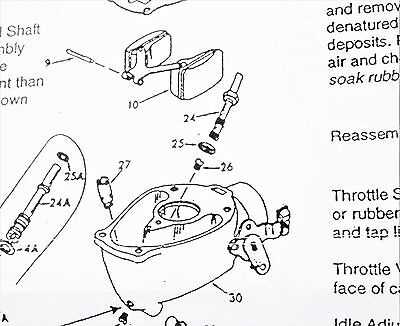
The needle valve and its corresponding seat play a crucial role in regulating the flow of fuel within the engine’s fuel delivery system. This mechanism is vital for maintaining optimal performance by ensuring that the correct amount of fuel enters the combustion chamber at the right time. Understanding how this component operates can help in troubleshooting fuel flow issues and enhancing engine efficiency.

Operation Principles

The needle valve operates by opening and closing in response to pressure changes within the system. When fuel pressure increases, the valve lifts off the seat, allowing fuel to flow through. Conversely, when the pressure decreases, the valve returns to its seated position, halting the flow. This on-off action creates a controlled environment for fuel delivery.

Importance of Proper Functioning

For optimal engine performance, the needle valve and seat must function effectively. Here are some key reasons why their proper operation is essential:

  • Fuel Regulation: Ensures a steady and appropriate fuel supply to the engine.
  • Preventing Flooding: Stops excessive fuel from entering the combustion chamber, which can lead to flooding and poor performance.
  • Efficiency: Contributes to better fuel efficiency by allowing precise control over fuel delivery.

Regular maintenance and inspection of these components are recommended to prevent issues that could compromise the engine’s operation. A malfunctioning needle valve can lead to symptoms such as poor acceleration, stalling, and increased emissions.

Idle Mixture Adjustment Parts

The proper tuning of fuel and air blend during idle conditions is crucial for optimal engine performance. Achieving the right balance ensures smooth operation and can significantly influence efficiency. Various components play a pivotal role in this adjustment, affecting how the mixture is regulated for a steady idle.

Adjustment Screws: These elements allow for fine-tuning of the fuel-air ratio. By turning the screws, users can increase or decrease the amount of fuel entering the system, leading to a richer or leaner mixture, respectively.

Needle Valves: Serving as a control mechanism, these valves help maintain the desired fuel level within the system. Their precise function ensures that the correct volume of fuel is delivered during idle, enhancing engine response.

Mixture Control Mechanism: This assembly regulates the overall blend of fuel and air. By adjusting this mechanism, users can optimize the idle settings, thereby improving engine stability and performance.

Spring Assemblies: These components assist in maintaining tension on the adjustment screws and needles. Proper spring tension is essential for the accurate operation of the mixture control system, ensuring consistent performance over time.

Understanding these elements is vital for anyone looking to maintain or enhance engine functionality. By focusing on the intricate details of each component, users can achieve a well-tuned engine that operates efficiently and reliably.

Common Wear and Replacement Parts
marvel schebler carburetor parts diagram

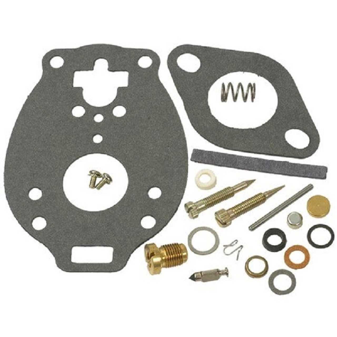
Over time, various components within an engine’s fuel delivery system may experience wear and require replacement to maintain optimal performance. Understanding which elements are most susceptible to deterioration can help ensure your engine runs smoothly and efficiently. Regular inspection and timely substitution of these components can prevent larger issues and extend the lifespan of your machinery.

Key Components Subject to Wear

Several crucial elements may show signs of wear due to continuous use and exposure to fuel and air mixtures. Seals and gaskets are particularly prone to degradation, often leading to air leaks that can affect engine performance. Additionally, float assemblies can become damaged, affecting the fuel level and flow, which can hinder proper engine operation. Regular checks can help identify these issues early.

Replacement Considerations
marvel schebler carburetor parts diagram

When replacing any worn components, it is vital to choose high-quality substitutes that match the specifications of the original design. Using premium materials not only ensures compatibility but also enhances the durability of the replacements. Furthermore, maintaining a routine inspection schedule can help detect wear patterns and facilitate proactive replacements, ultimately leading to improved engine reliability and efficiency.

Component Function