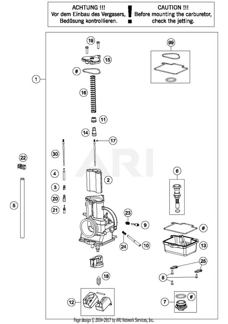
The intricate mechanisms that govern the delivery of fuel and air to an engine are crucial for its optimal performance. These systems play a vital role in ensuring the correct mixture reaches the combustion chamber, thereby influencing efficiency and power output. A detailed exploration of these elements reveals how each contributes to the overall functionality.
Within this complex assembly, various individual elements interact seamlessly to regulate airflow and fuel flow. Each component is meticulously designed to perform specific tasks, from controlling the mixture ratios to enhancing engine responsiveness. Understanding these distinct roles provides valuable insights into the engineering behind efficient combustion.
As we delve deeper into the various sections of this system, we will uncover the significance of each element, examining how they work in harmony. Recognizing the interplay between these components not only enhances our comprehension but also sheds light on the nuances of maintenance and troubleshooting, ultimately leading to a more efficient and reliable engine performance.
Understanding Carburetor Functionality
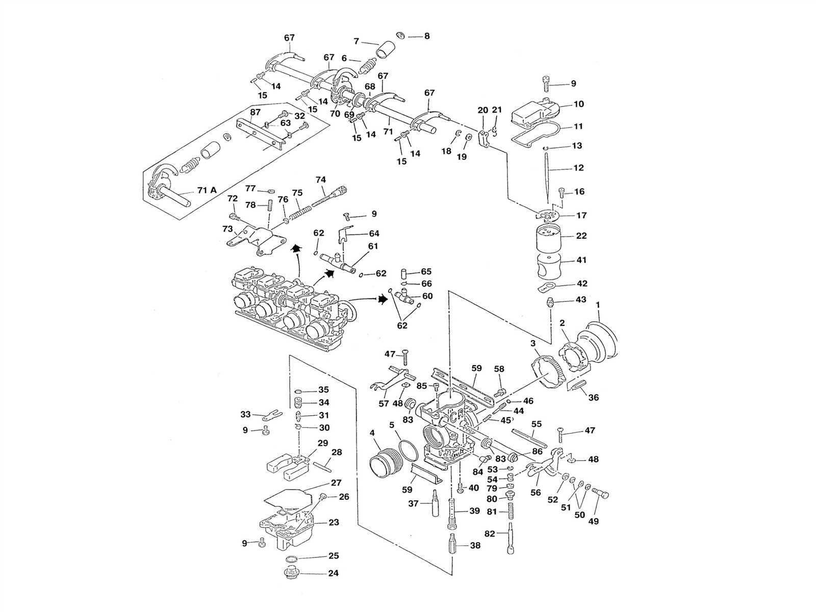
The operation of an essential engine component plays a critical role in ensuring optimal performance. This mechanism expertly blends fuel and air, enabling efficient combustion. By comprehending its functionality, one can appreciate its importance in the overall system.
At its core, this device relies on several key processes to achieve the desired mixture:
- Intake: Air is drawn in through an opening, creating a vacuum that facilitates the flow.
- Mixing: The incoming air interacts with fuel, creating a vaporized blend that is vital for combustion.
- Delivery: The mixture is directed into the engine cylinders, where it ignites to produce power.
Understanding these fundamental operations provides insight into the challenges and advancements in engine technology:
- Maintaining an optimal air-fuel ratio is crucial for efficiency.
- Variations in design can affect responsiveness and performance.
- Modern adaptations aim to enhance fuel economy and reduce emissions.
Grasping the intricacies of this critical component not only aids in troubleshooting but also informs decisions regarding upgrades and maintenance, ultimately leading to improved vehicle performance.
Key Components of a Carburetor
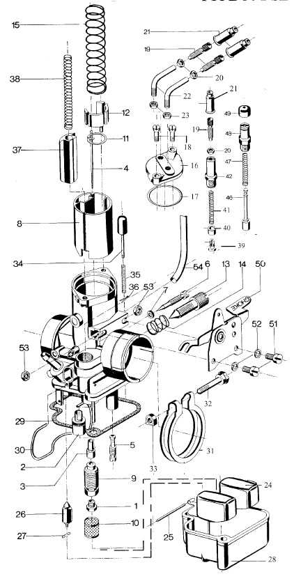
The functionality of an air-fuel mixing device hinges on several essential elements that work together to optimize engine performance. Each component plays a crucial role in ensuring a precise blend, influencing efficiency and power output.
The throttle body regulates airflow, controlling engine speed and acceleration. The fuel inlet delivers gasoline, while the float chamber maintains a consistent fuel level. Venturi, a narrowing passage, creates a pressure drop that draws fuel into the airstream, facilitating combustion. Additionally, jets meter the fuel flow, allowing for adjustments based on operational conditions.
Role of the Air-Fuel Mixture
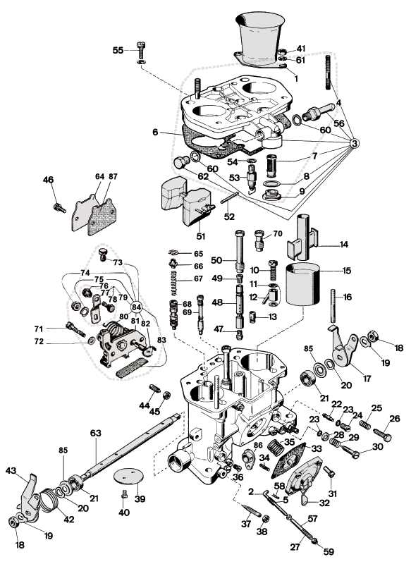
The combination of air and fuel is essential for the efficient operation of internal combustion engines. This blend is crucial for optimal performance, as it directly influences power output, fuel efficiency, and emissions. Understanding the significance of this mixture helps in maintaining engine health and ensuring smooth operation.
The proper balance between air and fuel is necessary for several reasons:
- Combustion Efficiency: A well-mixed combination promotes complete combustion, reducing unburned fuel and maximizing energy release.
- Engine Performance: An optimal ratio enhances throttle response and overall power delivery, making the engine more responsive.
- Emissions Control: Correct mixing helps minimize harmful emissions, contributing to a cleaner environment and compliance with regulations.
- Fuel Economy: Achieving the right mixture leads to better fuel utilization, reducing consumption and operational costs.
In summary, the air-fuel mixture plays a pivotal role in the functionality and efficiency of an engine. Maintaining the ideal ratio is critical for achieving peak performance and environmental compliance.
Types of Carburetors Explained
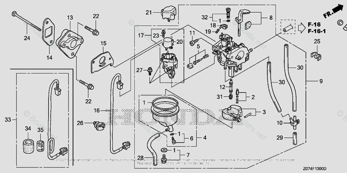
The various mechanisms designed to mix air and fuel in internal combustion engines can be categorized based on their design and functionality. Each type offers unique characteristics that cater to specific performance needs, allowing for enhanced efficiency and responsiveness in diverse applications.
Single-Barrel Systems
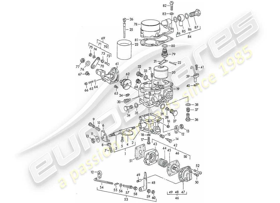
Single-barrel configurations are often found in smaller engines due to their simplicity and compact design. These systems provide adequate fuel-air mixtures for lower power outputs, making them ideal for everyday vehicles and light machinery. Their straightforward construction ensures ease of maintenance and operation.
Multi-Barrel Systems
Multi-barrel systems, which feature multiple mixing units, are utilized in high-performance engines requiring greater power and efficiency. These setups can deliver more air and fuel, enhancing acceleration and overall engine performance. Commonly seen in racing applications and powerful street vehicles, their complexity demands careful tuning to achieve optimal results.
Common Issues with Carburetors
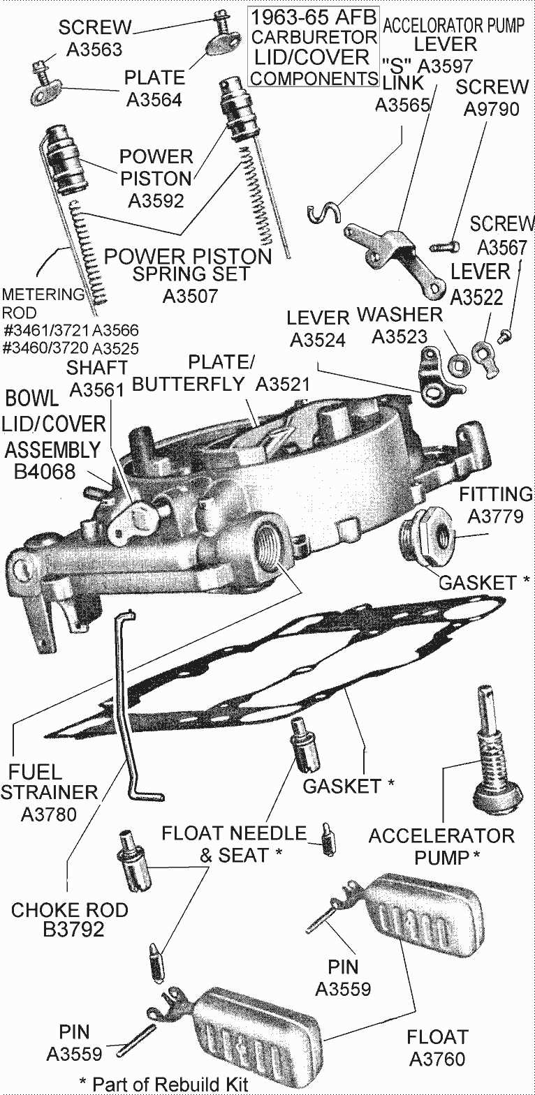
Numerous challenges can arise with fuel-air mixing devices that affect engine performance. Identifying and addressing these issues promptly can enhance efficiency and extend the lifespan of the engine. Below are some prevalent problems that users may encounter.
| Issue | Symptoms | Potential Causes |
|---|---|---|
| Stalling | Engine cuts out unexpectedly | Clogged jets or insufficient fuel supply |
| Hard starting | Difficulty igniting the engine | Improper air-fuel mixture or worn components |
| Poor acceleration | Delayed throttle response | Blocked air filter or dirty jets |
| Excessive fuel consumption | Frequent refueling needed | Leaking seals or incorrect adjustments |
| Backfiring | Unexpected loud noises from the exhaust | Rich mixture or ignition timing issues |
Regular maintenance and troubleshooting can significantly mitigate these problems, ensuring optimal performance and reliability over time.
Maintenance Tips for Longevity
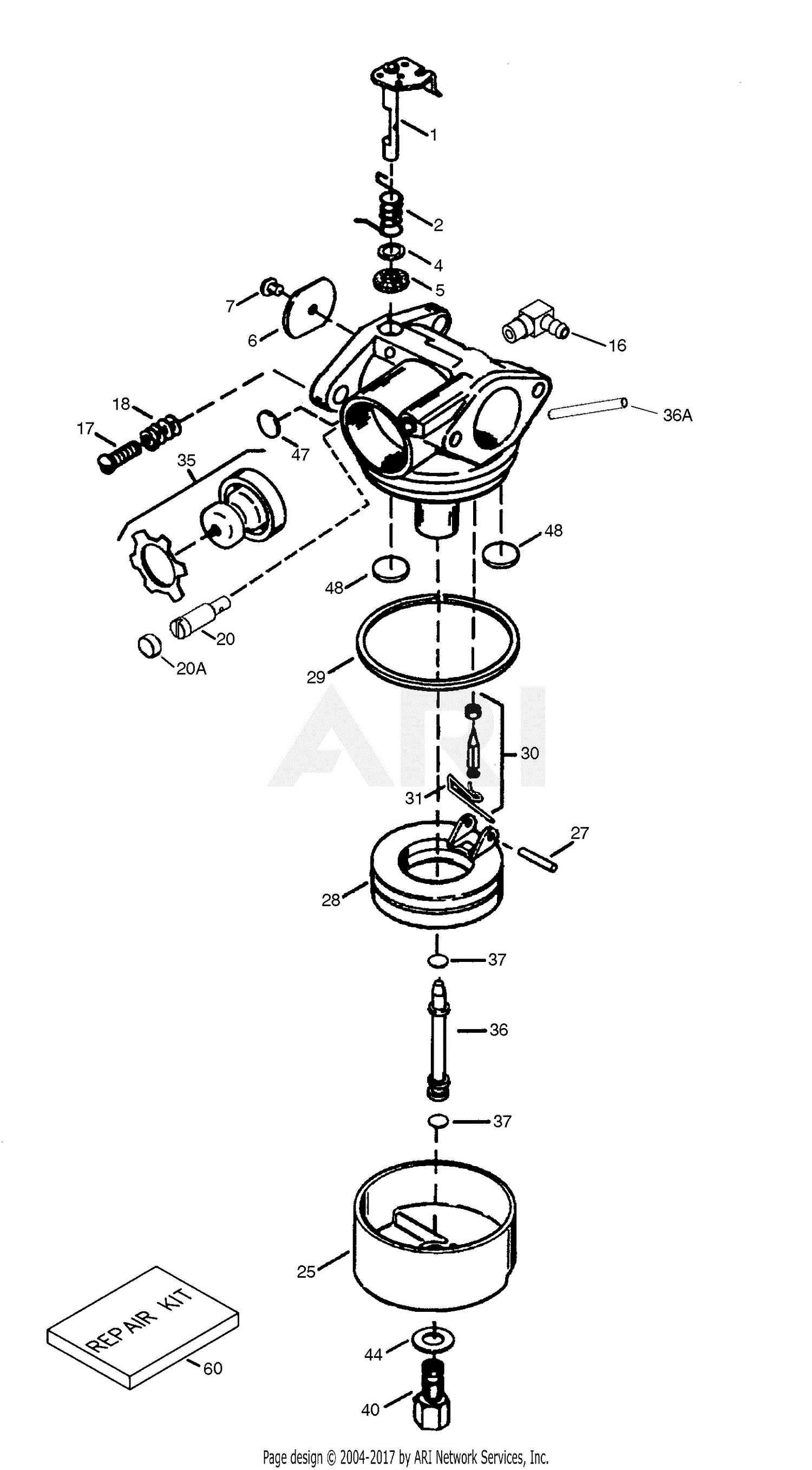
Proper upkeep is essential for ensuring the durability and efficiency of your engine’s fuel delivery system. Regular attention to specific aspects can greatly enhance its performance and lifespan.
- Regular Cleaning: Periodically clean components to remove dirt and debris that can impede function.
- Check Fuel Quality: Use high-quality fuel to prevent clogging and damage.
- Inspect Gaskets: Ensure seals are intact to avoid leaks and maintain pressure.
- Adjust Settings: Fine-tune air and fuel mixtures for optimal performance.
Implementing these practices can ultimately lead to a more reliable and efficient system, reducing the need for frequent repairs.
Impact on Engine Performance
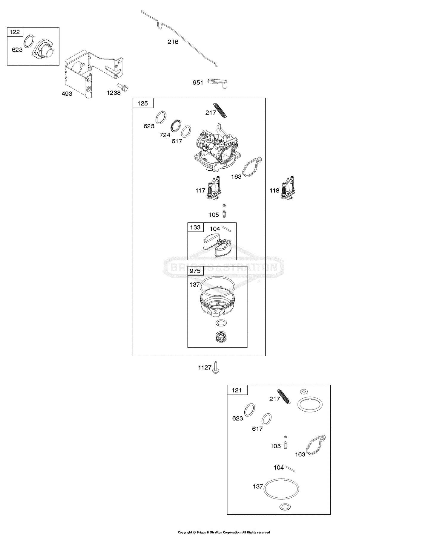
The efficiency and effectiveness of an internal combustion engine are significantly influenced by the way fuel and air are mixed and delivered. This interaction plays a crucial role in determining how well the engine performs, affecting power output, fuel efficiency, and overall responsiveness. Understanding this relationship is essential for optimizing engine operation and achieving desired performance levels.
Fuel-Air Mixture Quality
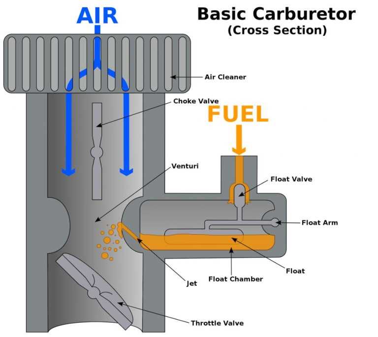
The quality of the mixture is paramount. A well-balanced blend ensures complete combustion, which maximizes power while minimizing emissions. If the ratio is off, it can lead to poor combustion, resulting in loss of power and increased fuel consumption. Proper tuning of this mixture can enhance performance and longevity of the engine components.
Influence on Throttle Response
The manner in which air and fuel are introduced to the combustion chamber directly affects throttle response. A swift and accurate delivery mechanism enhances the engine’s ability to accelerate promptly. Lagging response can hinder performance, causing frustration for drivers. Regular adjustments and maintenance can improve this critical aspect, ensuring that the engine behaves as intended under various driving conditions.
Visual Diagram of a Carburetor
This section aims to provide a clear representation of a crucial component in internal combustion engines, showcasing how various elements interact to ensure optimal performance. Understanding the layout and function of each element can significantly enhance one’s knowledge of engine mechanics.
Overview of the Components
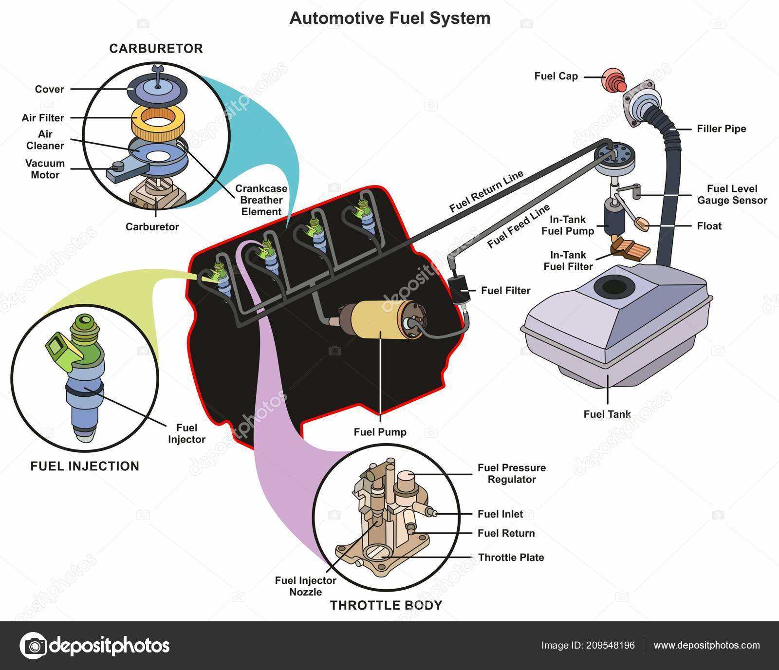
The visual representation highlights the essential sections that contribute to fuel and air mixture delivery. Each section plays a vital role, from controlling airflow to regulating fuel flow, ultimately influencing engine efficiency and power output.
Functional Relationships
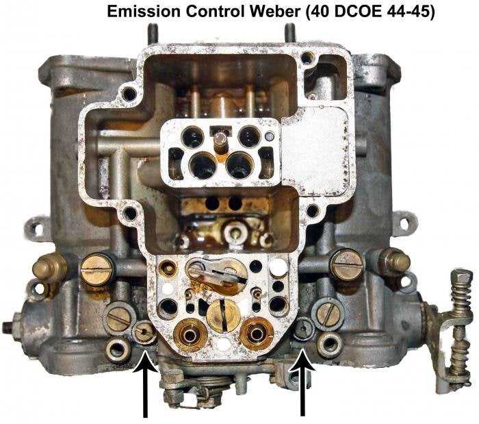
Examining the interactions between the depicted sections reveals how adjustments in one area can impact overall functionality. Such insights are invaluable for troubleshooting and optimizing engine performance, making it easier to diagnose issues and implement effective solutions.