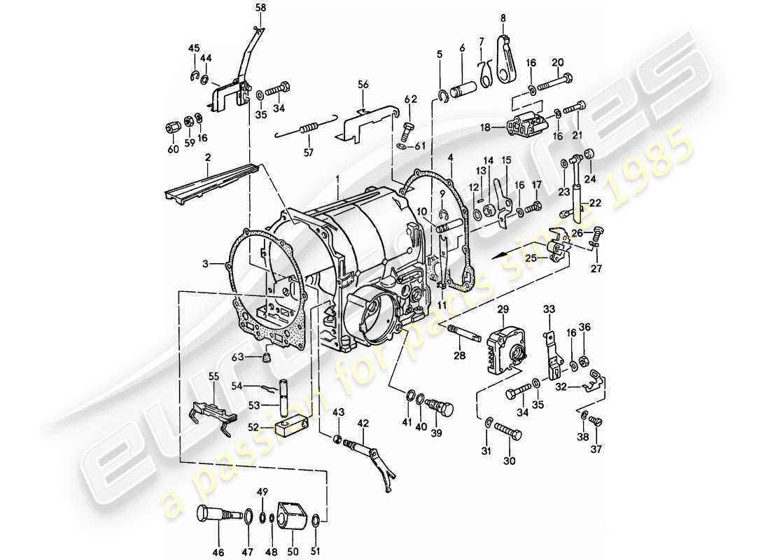
The intricate mechanisms that enable vehicles to shift between different speed ranges rely on a complex assembly of components. These elements work together to ensure smooth transitions and optimal performance during various driving conditions. Understanding the relationship between these elements is crucial for anyone looking to gain insight into how different speeds are achieved within a vehicle’s engine system.
Each component plays a specific role, from managing power distribution to controlling torque. These elements ensure that the energy from the engine is efficiently transferred to the wheels, allowing for precise control over acceleration and deceleration. By examining the structure and function of these components, one can gain a deeper appreciation for the engineering involved.
The following section offers a breakdown of the key elements that contribute to the system’s overall operation. Exploring how these parts interact can help in both diagnosing potential issues and improving the efficiency of the overall mechanism.
Understanding the Layout of a Manual Gearbox
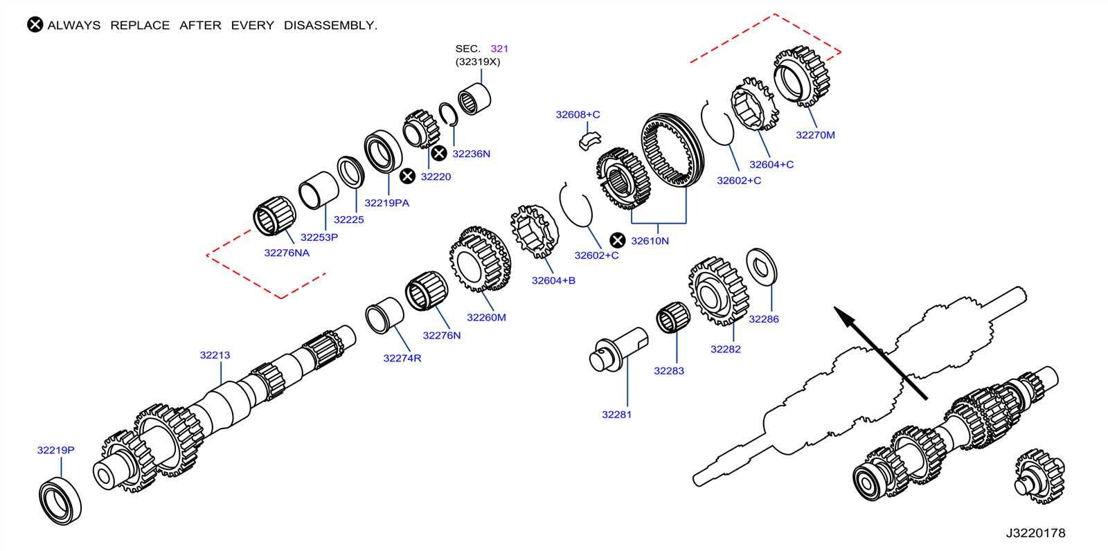
The structure of this mechanical system is designed to control the vehicle’s power flow, optimizing the connection between the engine and the wheels. Each component plays a role in ensuring that the driver can smoothly adjust the speed and torque delivered to the wheels, allowing for a wide range of motion and adaptability.
Key Components Overview
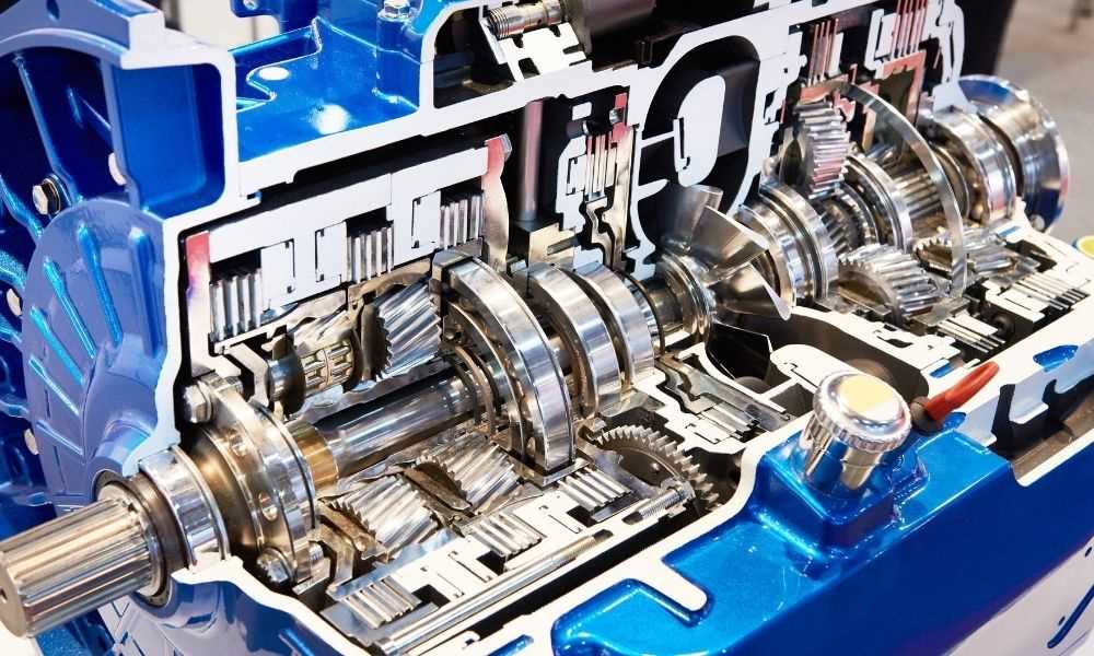
The layout includes several interdependent parts that collaborate to shift through different operational levels. This system uses gears, shafts, and synchronizers to regulate the movement effectively. Understanding these core elements is essential to grasp how power is transferred.
- Input shaft: This component receives force from the engine and initiates the process.
- Output shaft: Transfers the adjusted force to the wheels, controlling speed.
- Synchronizers: Enable smooth engagement between different gears, preventing rough transitions.
- Selector forks
Key Components of a Standard Transmission System
A standard gear mechanism is an intricate assembly that relies on various interconnected elements working in harmony to transfer power from the engine to the wheels. Each component plays a crucial role in ensuring smooth operation and adapting the power flow to different driving conditions. Understanding these core elements helps to appreciate the complex engineering behind the system.
Gearbox: The gearbox contains a set of gears that modify the rotational force to match the vehicle’s speed and power requirements. This allows the system to adjust torque, providing the necessary strength for different driving scenarios.
Clutch: The clutch enables the driver to disconnect the power source from the rest of the system when shifting between gears. It acts as a buffer, ensuring smooth engagement and disengagement without damaging the machinery.
Driveshaft: The driveshaft is a long, rotating component that transfers power from the engine to the wheels. It connects various parts, ensuring that rotational energy is delivered effectively to move the vehicle forward.
Synchronizers: Synchronizers ensure that gears can be changed without causing damage to
Role of the Clutch in Gear Shifting
The clutch plays a critical role in enabling smooth transitions between different speed stages in a vehicle. It is responsible for temporarily disconnecting the power from the engine, allowing the driver to select a new speed setting without damaging the system. The clutch ensures that this process is efficient and reduces wear on key components.
How the Clutch Functions
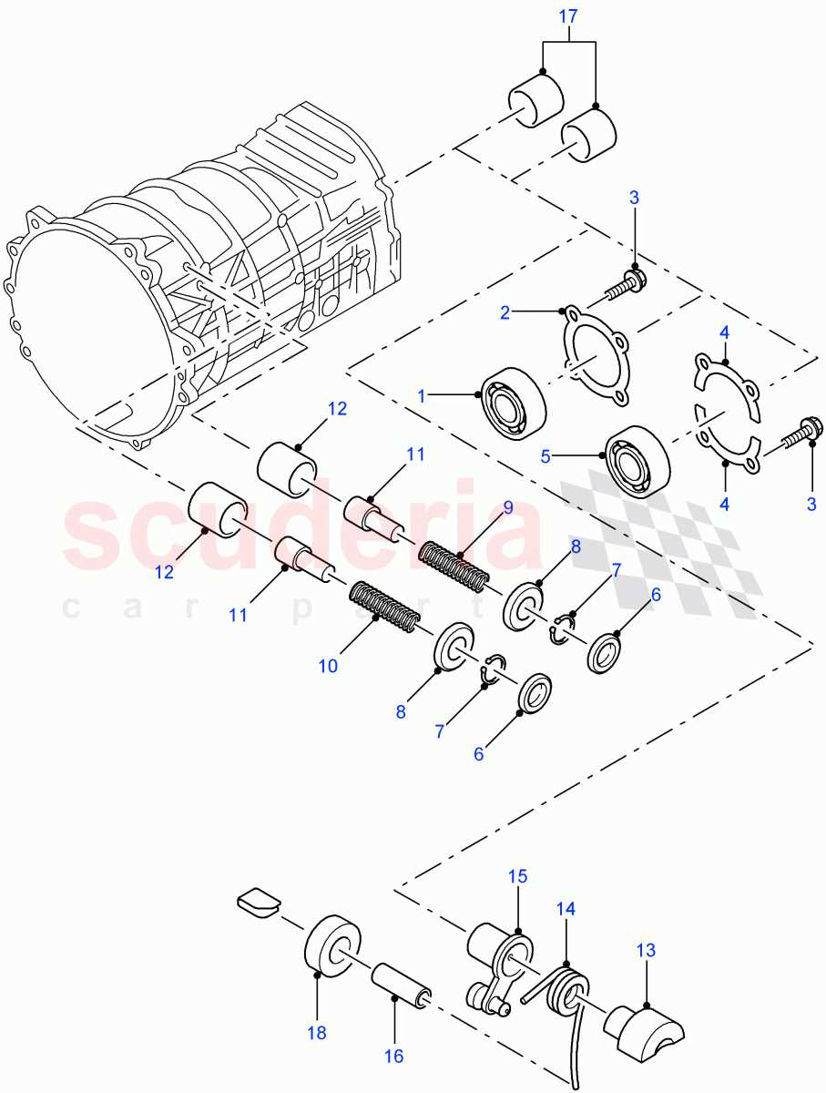
When the driver presses the clutch pedal, it disengages the power source from the drivetrain, allowing the change to occur. Without this separation, moving between speed stages would be difficult and could lead to significant mechanical issues.
- Pressing the pedal disconnects the power transfer.
- It allows for a smoother transition between gears.
- Releasing the pedal re-engages the power to the wheels.
Importance of Timing
Proper timing of engaging and disengaging the clutch is essential to ensure
Exploring the Function of the Shift Fork
The shift fork plays a crucial role in enabling smooth operation within the gear system. Its primary purpose is to control the movement of key components, allowing for the selection and engagement of different driving modes. This mechanism ensures that changes between gears occur seamlessly and with precision.
How the Shift Fork Engages Gears
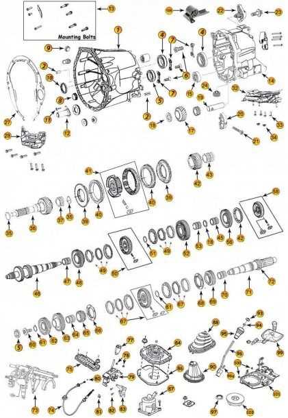
When activated, the shift fork moves a specific element within the gear assembly. This movement directs other components to engage or disengage, making it possible to change driving speeds. Its design ensures that these transitions happen efficiently, preventing unnecessary wear or damage.
The Precision of Gear Shifts
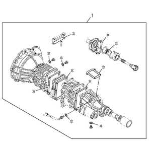
The accuracy of the shift fork is vital for optimal performance. By guiding the movement of internal components, it allows for smooth and precise transitions between gear positions, contributing to the overall reliability and durability of the system.
Synchronization Process within the Transmission
The synchronization system ensures smooth operation by matching the speed of rotating elements, allowing for a seamless shift between gears. It prevents grinding and reduces wear by aligning the rotating components before they engage. This process relies on precisely engineered mechanisms that work in harmony to maintain fluidity during changes in speed.
Key Components of the Synchronization System
The core of the system includes synchronizer rings, which are responsible for adjusting rotational speeds. These rings, made from durable materials, use friction to align the moving parts before engagement. Alongside them, the hub and sleeve assembly help guide and lock the gears in place once the speeds are synchronized, ensuring a stable connection.
How the Synchronization Works
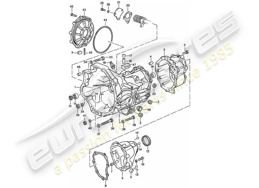
When a gear shift is initiated, the synchronizer pushes against the corresponding element, slowing down or speeding up the rotation. Once both speeds match, the hub slides into place, allowing the shift to occur without resistance. This process happens in a fraction of a second, making gear changes feel almost instantaneous. By maintaining proper synchronization, the system ensures longevity and optimal performance.
Gears and Their Role in Speed Control
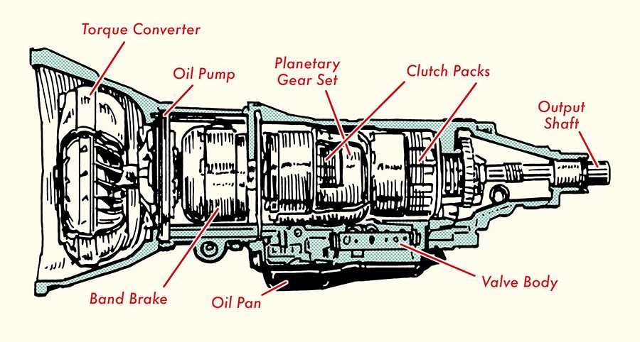
The intricate arrangement of gears plays a crucial role in managing velocity within various mechanisms. Each gear, varying in size and tooth configuration, contributes to the overall functionality by altering rotational speed and torque. This interaction not only defines the pace at which a vehicle moves but also enhances the efficiency of power transfer from the engine to the wheels.
Understanding Gear Ratios
Gear ratios determine how the rotation of one gear affects another. When two gears engage, the size difference between them dictates the output speed. A smaller gear turning a larger one will reduce speed while increasing torque, making it ideal for acceleration. Conversely, pairing a larger gear with a smaller one results in higher speed but lower torque, suitable for cruising at high velocities.
The Impact of Gear Selection
Choosing the appropriate gear is vital for optimal performance. The driver must consider various factors, such as road conditions and desired speed. Engaging lower gears facilitates better control during climbs or challenging terrains, while higher gears are advantageous for maintaining speed on level surfaces. This adaptability is essential for achieving a balance between power and efficiency.
Transmission Housing and Its Importance
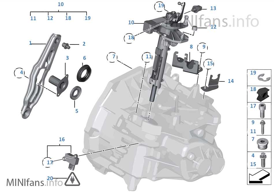
The outer casing of a gear system serves a crucial role in the overall functionality and performance of a vehicle. This component acts as a protective barrier, housing various internal elements that facilitate the operation of the vehicle’s movement. Its significance extends beyond mere containment, influencing several aspects of performance and durability.
Key reasons for the importance of this casing include:
- Protection: It safeguards internal mechanisms from environmental factors such as dirt, moisture, and debris, which can lead to wear and tear.
- Structural Integrity: The robust design ensures that the inner components remain securely in place during operation, minimizing vibrations and potential damage.
- Heat Dissipation: Efficient heat management is essential for optimal performance. The housing aids in dissipating heat generated during operation, preventing overheating.
- Fluid Containment: It holds essential lubricants that reduce friction among moving parts, ensuring smooth operation and extending the lifespan of the assembly.
Understanding the role of this outer shell helps in recognizing its impact on the efficiency and reliability of a vehicle, making it a critical focus for maintenance and engineering considerations.
How the Output Shaft Drives the Vehicle
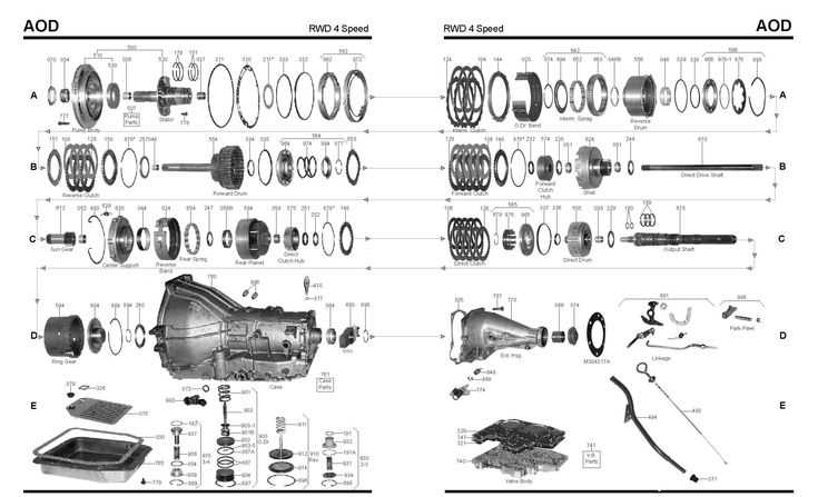
The output shaft plays a crucial role in the movement of a vehicle, acting as a key component in transferring energy from the engine to the wheels. This element is designed to convert the rotational force generated by the engine into a usable motion that propels the vehicle forward or backward.
When the engine generates power, this energy travels through various mechanisms before reaching the output shaft. As the shaft rotates, it engages with the components that connect to the wheels, ensuring that the vehicle can achieve the desired speed and acceleration. The efficiency of this process is essential, as it directly influences the vehicle’s performance and handling.
Additionally, the output shaft is equipped with features that allow for smooth transitions between different driving conditions. Whether accelerating from a standstill or navigating sharp turns, this element adapts to the demands of the road, ensuring a seamless driving experience. Its design and functionality are fundamental to the overall operation of the vehicle.
Identifying Common Issues in Transmission Parts

Recognizing the typical challenges encountered in the inner workings of a vehicle’s gearing system is essential for maintaining optimal performance. Various symptoms may indicate underlying troubles, necessitating careful inspection and analysis to ensure the smooth operation of the vehicle.
Wear and Tear: Over time, components can experience degradation due to regular use. This wear can lead to misalignment and inefficient operation, resulting in a decrease in overall functionality.
Fluid Leaks: A common issue arises when hydraulic fluids escape from their designated areas. This leakage can severely affect the performance and longevity of the system, requiring immediate attention.
Unusual Noises: Strange sounds during operation often signal potential malfunctions. Grinding, whining, or clunking noises can indicate problems with the interaction between various components, pointing to the need for further investigation.
Difficulty Engaging: If there is trouble shifting between gears, this may suggest an issue with the engagement mechanism. Such difficulties can stem from worn components or inadequate lubrication, both of which require prompt resolution.
By being vigilant and aware of these common indicators, vehicle owners can take proactive measures to address issues, ensuring a smoother and safer driving experience.