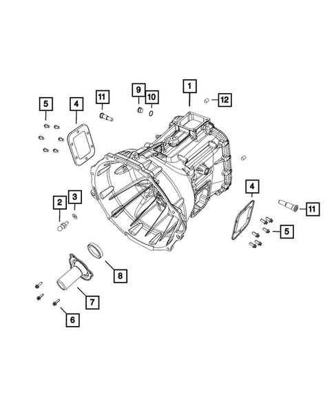
The efficiency and functionality of any vehicle significantly depend on the intricate network of mechanisms responsible for transferring power from the engine to the wheels. This complex interplay ensures that the energy generated by the engine is effectively converted into motion, allowing for a smooth and responsive driving experience.
At the heart of these systems lies a variety of crucial elements, each playing a specific role in the seamless operation of the entire assembly. From the engagement of gears to the modulation of torque, these components work in unison to optimize performance and enhance reliability.
Exploring the intricacies of these mechanisms not only sheds light on how vehicles operate but also underscores the importance of maintenance and understanding of each element. A deeper insight into these systems can aid enthusiasts and professionals alike in troubleshooting and enhancing vehicle performance.
Understanding Diagram Transmission Systems
This section delves into the intricate mechanisms that facilitate the transfer of energy and motion within various machines. By examining these frameworks, we can gain insights into their operation, efficiency, and applications in diverse fields. Understanding these systems is crucial for optimizing performance and ensuring longevity in mechanical designs.
Key Components and Their Functions
At the heart of these mechanisms are several essential components, each playing a vital role in the overall functionality. Gears, for instance, are instrumental in altering speed and torque, while shafts serve as conduits for transferring force from one element to another. Other elements, such as clutches and bearings, are equally important, contributing to the smooth operation and control of movement within the system.
Applications in Various Industries
The principles governing these systems are employed across numerous sectors, from automotive engineering to industrial machinery. Understanding the design and interplay of these components allows engineers to create more efficient and reliable machines, ultimately leading to enhanced productivity and reduced operational costs. As technology continues to evolve, so too will the innovations in these essential systems.
Key Components of Transmission Diagrams
Understanding the essential elements that contribute to the functionality of gear systems is crucial for grasping how they operate. Each component plays a vital role in the overall mechanism, ensuring that power is efficiently transferred through various stages. This section delves into the main elements that form the backbone of these intricate systems.
Main Elements
The core components include various gears, shafts, and auxiliary elements that work together in a cohesive manner. Each part has a specific function, and their interactions determine the efficiency and effectiveness of the entire assembly.
Table of Essential Components
| Component | Description |
|---|---|
| Gears | Mechanisms that transmit rotational force and control speed. |
| Shafts | Rod-like elements that transfer torque between components. |
| Bearings | Support structures that reduce friction and allow smooth movement. |
| Clutches | Devices that engage and disengage the connection between moving elements. |
| Synchronizers | Mechanisms that ensure smooth gear shifting by matching speeds. |
By comprehensively understanding these critical elements, one can appreciate the intricacies involved in mechanical systems, leading to improved design and maintenance practices.
Types of Transmission Diagrams Explained
The exploration of different visual representations in the context of mechanical systems reveals a wealth of information about their functionality and structure. These illustrations serve as essential tools for understanding how various components interact, showcasing the flow of energy and movement within a system. Each type of visual representation offers unique insights that cater to specific needs and perspectives.
Flow Charts are designed to depict the sequential steps in a process. They clarify how power is transferred from one component to another, helping engineers and technicians visualize operational sequences. These charts are particularly useful for troubleshooting and optimizing performance.
Component Layouts focus on the spatial arrangement of elements within a system. They provide a clear overview of how individual units are positioned relative to one another, aiding in the design and maintenance of mechanical assemblies. Understanding this layout is crucial for ensuring efficient assembly and disassembly.
Schematic Representations emphasize the functional relationships between components. These illustrations break down complex interactions into simpler forms, making it easier to analyze and understand how energy flows through the system. They are invaluable in educational contexts and for engineers designing new solutions.
Block Diagrams simplify systems into basic elements connected by lines that represent relationships. This abstraction helps in conceptualizing the overall functionality without getting lost in intricate details. They are particularly effective for high-level analysis and communication among teams.
Understanding these various visual formats enhances comprehension of mechanical systems, enabling professionals to effectively communicate ideas and solutions. Each representation serves its purpose, providing distinct advantages depending on the context of use.
Importance of Accurate Diagrams in Engineering
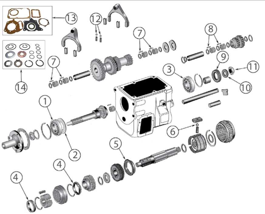
In the realm of engineering, the precision of visual representations plays a critical role in the successful execution of projects. These illustrations serve as a bridge between complex concepts and practical applications, enabling professionals to communicate intricate ideas clearly and effectively. When designed with care, they can enhance understanding and streamline the development process, ultimately leading to more efficient outcomes.
Facilitating Communication
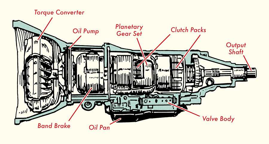
Clear visual models promote effective dialogue among team members, stakeholders, and clients. When everyone can reference a unified visual tool, the likelihood of misunderstandings diminishes significantly. This clarity fosters collaboration and ensures that all parties are aligned with the project’s objectives, reducing the risk of costly errors and delays.
Supporting Problem Solving
Accurate representations aid in identifying potential challenges early in the design process. By providing a detailed overview of the components involved, these tools allow engineers to anticipate issues and devise solutions before they escalate. This proactive approach not only saves time but also enhances the overall quality of the final product, ensuring it meets the required standards and specifications.
Common Issues in Transmission Diagrams
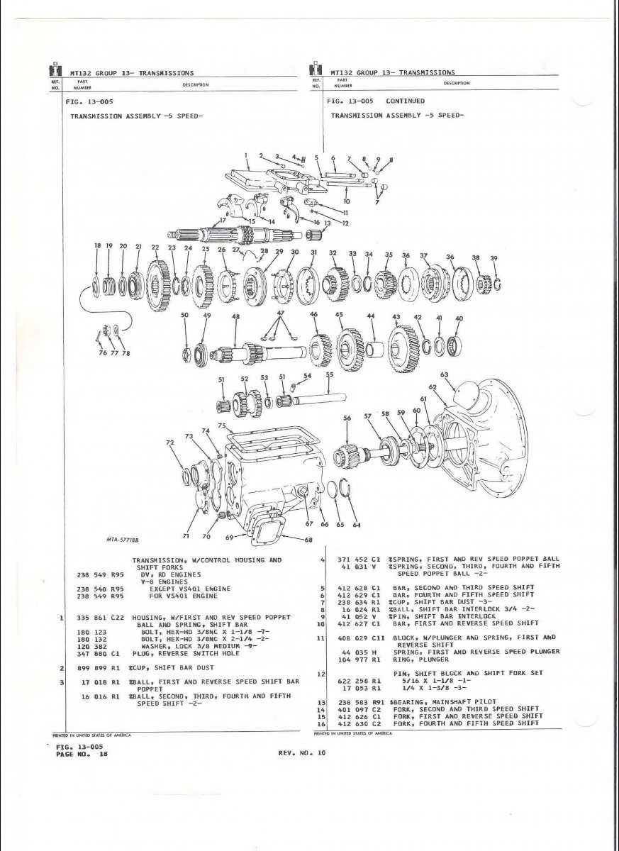
Understanding the complexities of mechanical systems can often be hindered by inaccuracies and misunderstandings in visual representations. These representations are crucial for conveying the relationships and functions of various components. However, several frequent problems can arise, affecting the clarity and effectiveness of these illustrations.
- Ambiguity in Symbols: Inconsistent or unclear symbols can lead to confusion, making it difficult for users to interpret the information correctly.
- Incorrect Scale: A lack of proportionality may distort the actual sizes and relationships of components, complicating the assembly or troubleshooting processes.
- Omission of Details: Missing elements can result in incomplete understanding, leading to potential errors during installation or maintenance.
- Overcomplicated Layouts: Excessive information or cluttered visuals can overwhelm users, making it challenging to focus on critical aspects.
- Poor Labeling: Ineffective or missing labels can obscure vital information, causing misinterpretation of the system’s functionality.
Addressing these issues is essential for enhancing clarity and usability, ensuring that users can effectively navigate and comprehend the intricacies of the system being represented.
How to Read Transmission Diagrams
Understanding intricate schematics can significantly enhance your ability to diagnose and repair mechanical systems. Familiarity with symbols and layouts is crucial for interpreting these illustrations effectively. This section provides insights into the essential components and methodologies needed to comprehend these visual representations.
To start, it’s important to recognize the various symbols used in these illustrations. Each symbol represents a specific component, and knowing what they signify allows for quicker navigation through the layout. Familiarize yourself with a legend or key that accompanies the schematic, as it provides a reference for understanding the various elements depicted.
| Symbol | Description |
|---|---|
| ◼ | Connection point |
| → | Flow direction |
| ⚙ | Gear or mechanism |
| ❌ | Disconnection point |
Next, pay attention to the flow of energy or movement indicated in the visual. Arrows often illustrate the direction in which components interact or transfer power. Understanding this flow is essential for troubleshooting and optimizing the system.
Finally, practice is key. Regularly engaging with these visuals will build your confidence and proficiency in reading them. The more familiar you become with the layout and symbols, the easier it will be to diagnose issues and implement solutions efficiently.
Tools for Creating Transmission Diagrams
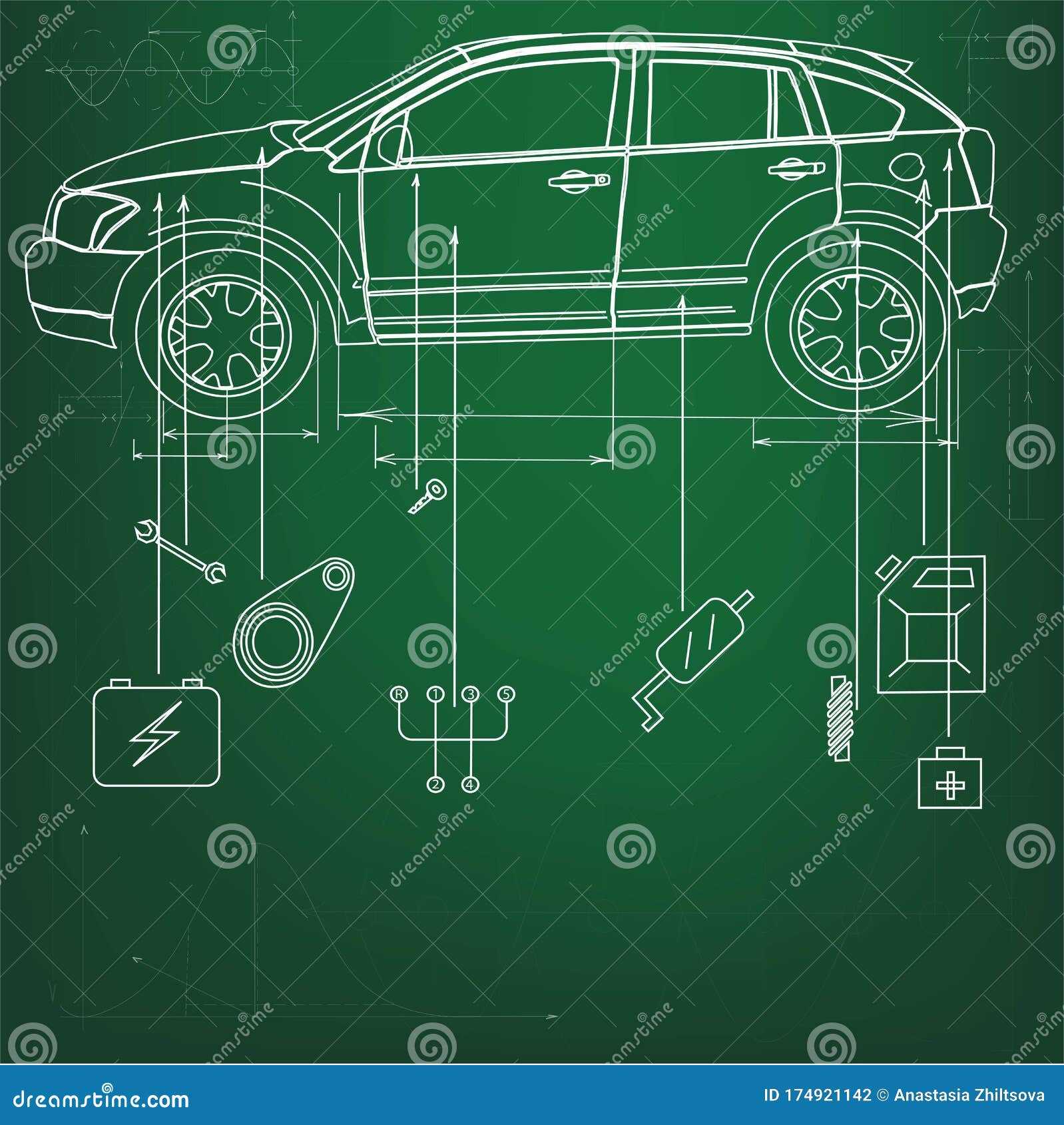
In the realm of engineering and design, the visualization of complex systems is crucial for effective communication and understanding. Various instruments facilitate the illustration of mechanical structures, enabling professionals to convey intricate relationships and functionalities. These resources range from traditional manual techniques to advanced software applications.
Software Solutions: Numerous software packages provide intuitive interfaces for crafting detailed visual representations. Programs such as AutoCAD and SolidWorks allow users to design intricate layouts with precision. These tools often come equipped with libraries of symbols and components, streamlining the creation process and enhancing accuracy.
Online Platforms: Web-based applications have emerged as accessible alternatives for those seeking simplicity and collaboration. Tools like Lucidchart and Draw.io enable users to work in real-time, sharing their creations with teams regardless of location. Such platforms often feature templates that assist in expediting the design process.
Manual Techniques: For those who prefer a hands-on approach, traditional drafting methods still hold value. Utilizing graph paper, pencils, and rulers can foster a deeper understanding of spatial relationships. This method encourages creativity and can lead to innovative solutions that digital tools may not readily facilitate.
By leveraging these various resources, engineers and designers can effectively illustrate mechanical configurations, ultimately enhancing clarity and fostering better collaboration within their projects.
Case Studies in Diagram Applications
This section explores practical examples where visual representations have played a crucial role in various industries. By analyzing these case studies, we can better understand how structured visuals enhance communication, streamline processes, and facilitate problem-solving.
One notable example comes from the automotive sector, where schematic representations are used extensively during the design and assembly phases. A major manufacturer implemented detailed visuals to map out workflows, resulting in a 20% reduction in assembly time. This approach allowed teams to identify potential bottlenecks and improve efficiency significantly.
In the field of software development, a tech company adopted visual tools to illustrate system architecture and data flow. This strategy not only improved collaboration among developers but also reduced errors during coding by providing a clear framework. As a result, the team completed projects faster and with higher accuracy.
Healthcare is another area where graphical representations have made a substantial impact. A hospital utilized flowcharts to optimize patient care pathways, leading to shorter wait times and enhanced service delivery. By visualizing processes, staff could easily pinpoint areas needing improvement and implement changes effectively.
Lastly, in the education sector, an institution integrated visual aids into its curriculum to enhance student comprehension. The use of structured visuals in lessons helped students grasp complex concepts more quickly, leading to improved academic performance. This approach highlights the power of imagery in facilitating learning and retention.
Future Trends in Transmission Design
As the automotive industry evolves, innovative approaches are reshaping how power is delivered from the engine to the wheels. Engineers are increasingly focused on enhancing efficiency, performance, and sustainability, pushing the boundaries of traditional systems.
Electrification is at the forefront of these advancements. With the rise of electric and hybrid vehicles, traditional mechanical systems are being replaced or supplemented by electric drivetrains. This shift not only improves energy efficiency but also allows for greater design flexibility and reduced weight.
Smart technologies are also transforming how vehicles operate. Integrating advanced sensors and real-time data analytics enables more responsive and adaptive systems. These innovations enhance the driving experience while optimizing performance under various conditions.
Moreover, the emphasis on sustainability is driving the development of lighter, more efficient components. Utilizing recyclable materials and innovative manufacturing processes helps reduce the environmental impact, aligning with global efforts to combat climate change.
As we look to the future, these trends will likely continue to redefine how power is managed in vehicles, leading to more efficient, powerful, and environmentally friendly transportation solutions.