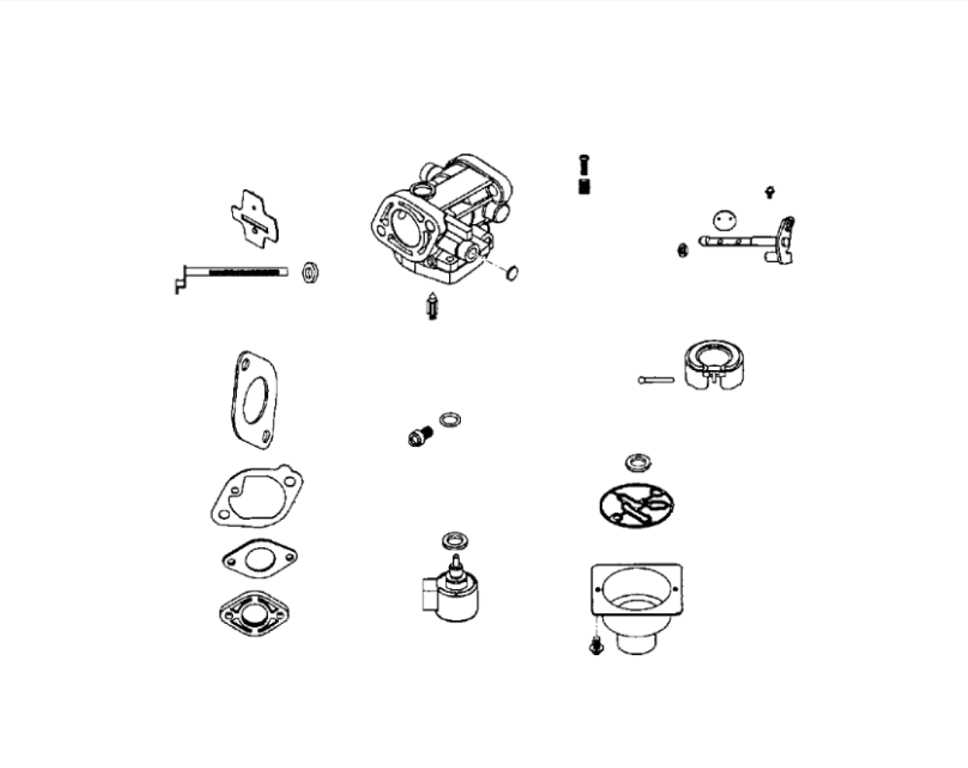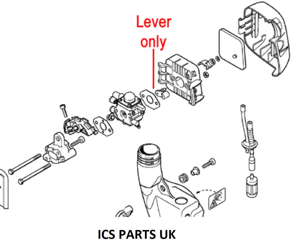
The detailed arrangement of the internal and external elements of the BG 86 device plays a crucial role in ensuring its efficient performance. Understanding the structure allows for smoother operation and easier identification of key features, which are essential for proper upkeep.
Focusing on the intricate organization of various mechanisms, this guide provides insight into the positioning and function of each section. Familiarity with these details enables timely maintenance and troubleshooting, ensuring the equipment continues to work at its best.
By exploring the specific layout and arrangement, users can better navigate the system and enhance their experience when dealing with technical issues or routine care. This understanding is vital for extending the life and efficiency of the equipment.
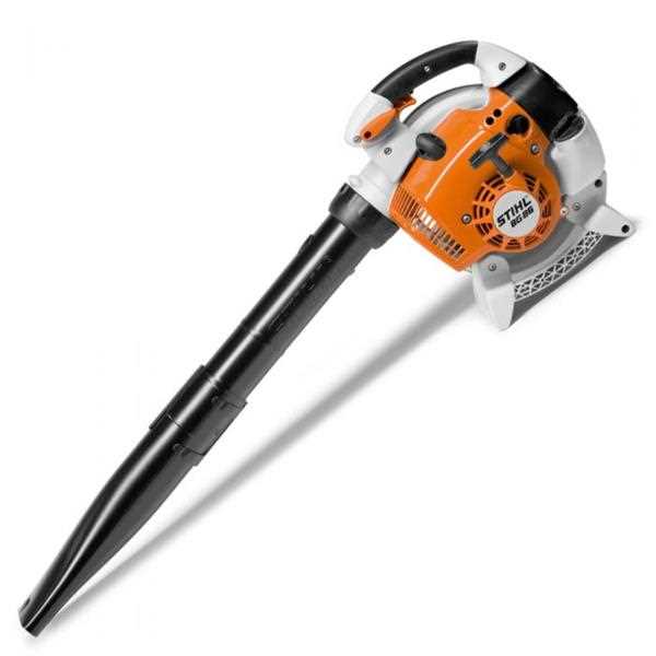
Key Components of the Stihl Blower BG 86
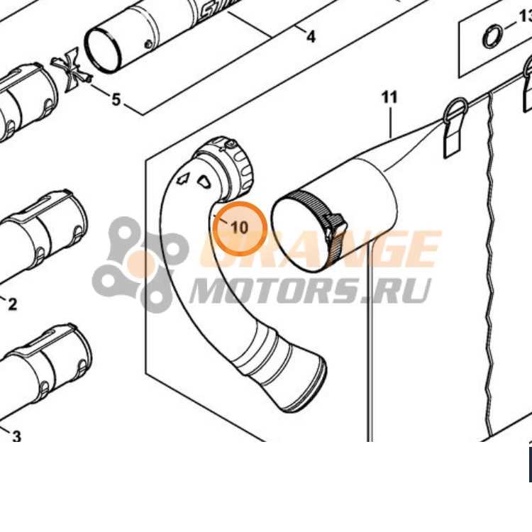
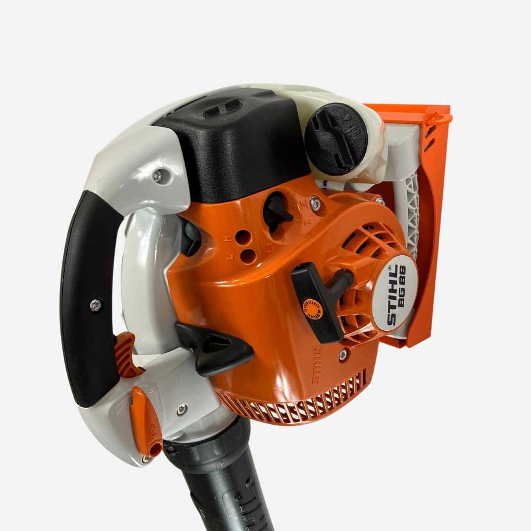
The equipment is composed of several crucial elements that work together to provide effective functionality. Each part plays a significant role in ensuring optimal performance, making it essential to understand the purpose of these elements for maintenance and operation.
One of the core components is the engine, which provides the necessary power. Additionally, the air intake and exhaust systems contribute to airflow efficiency, while the fuel tank ensures continuous operation. The nozzle directs the air, maximizing output, and the handle offers user control and comfort during operation. Together, these elements form a reliable and efficient tool.
Engine Assembly Breakdown for BG 86
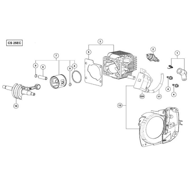
The engine of the BG 86 model is a complex system designed for optimal performance and longevity. In this section, we will explore the essential components that contribute to the engine’s functionality. Understanding how each element fits and interacts will help you maintain and service your equipment efficiently.
| Component | Description |
|---|---|
| Cylinder | Central part of the engine where combustion occurs, generating power for the device. |
| Piston | Moves within the cylinder, creating the necessary force to operate the engine. |
| Crankshaft | Transforms the linear motion of the piston into rotational motion. |
| Flywheel | Maintains engine momentum and helps ensure smooth operation during power cycles. |
| Spark Plug | Ign
Fan and Housing Structure Overview
The design of the fan and housing components plays a crucial role in the performance and efficiency of various machines. This section focuses on the key elements that make up this structure, highlighting how they work together to deliver optimal air movement. The interaction between the fan blades and the surrounding housing ensures smooth and controlled airflow, essential for effective operation.
Ignition System Parts and Functions
The ignition mechanism plays a crucial role in the operation of many machines, ensuring the correct sequence of electrical impulses to start and maintain engine function. Without a properly working ignition setup, the equipment would not be able to achieve smooth and efficient performance. Main Components
The core elements include devices responsible for generating and distributing electrical energy. These components work together to initiate combustion by creating a spark at the right moment. Spark plugs and ignition coils are vital in converting electrical energy into the necessary spark for starting the engine. Functions of Key Elements
Each element within the system has its specific role. For instance, the ignition coil transforms low voltage from the power source into a higher voltage, crucial for spark plug operation. Meanwhile, the spark plug itself delivers this spark, igniting the air-fuel mixture within the engine. Throttle Control Mechanism and Layout
The throttle control system is designed to regulate the engine’s power output by adjusting airflow and fuel mixture. Its layout consists of interconnected components that allow for smooth operation and precise control. Understanding the arrangement of these elements is essential for efficient use and maintenance. Main Components of the Throttle System
Throttle Linkage and Operation
The linkage connects the control lever to the carburetor, allowing for adjustments to the airflow. Proper alignment of this linkage ensures that the system responds efficiently, providing accurate control over the engine’s performance.
The arrangement of the fuel reservoir and the associated conduits is essential for optimal performance in any outdoor power equipment. This system ensures the proper delivery of fuel to the engine, facilitating efficient combustion and operation. Understanding the components involved helps in maintaining and troubleshooting the unit effectively. The fuel tank is designed to store the necessary liquid while providing a secure and accessible way to refill when needed. It is typically made of durable materials that can withstand exposure to various environmental conditions. The fuel line, on the other hand, connects the tank to the engine, allowing for the flow of fuel during operation. This line must be free of obstructions and leaks to ensure consistent performance. Moreover, the configuration may include various fittings and connectors that enhance the overall integrity of the fuel delivery system. Regular inspection and maintenance of these components can prevent potential issues, leading to smoother operation and extended lifespan of the equipment. Air Filter and Carburetor Placement
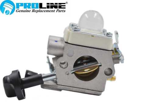
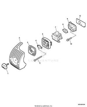
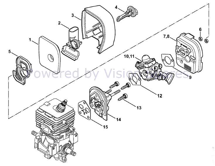
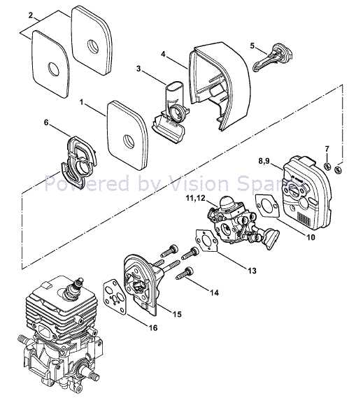
The configuration of the air filtration and fuel mixing systems is crucial for the efficient performance of outdoor power equipment. Properly positioning these components ensures optimal airflow and fuel delivery, contributing to enhanced engine functionality and longevity. Understanding Air Filter Location
The air filter serves to keep impurities from entering the engine. Its placement is designed to maximize air intake while minimizing exposure to dirt and debris. Here are some key points regarding its positioning:
Carburetor ArrangementThe carburetor is essential for mixing air and fuel in the correct ratio for combustion. Its strategic placement enhances efficiency and responsiveness. Consider the following aspects:
Muffler and Exhaust System Layout
The muffler and exhaust system play a crucial role in the overall performance and efficiency of an engine. This component is responsible for reducing noise and directing harmful gases away from the engine and operator. Understanding the layout of these elements is essential for maintenance and repair. The following are key aspects of the exhaust configuration:
A well-designed exhaust system not only contributes to the machine’s efficiency but also protects the environment by reducing emissions. Regular inspections and timely repairs are vital for maintaining optimal performance. Maintenance Tips for BG 86 Replacement PartsEnsuring the longevity and optimal performance of your equipment requires attention to detail and regular upkeep. Proper care of individual components can significantly enhance functionality and extend the lifespan of your machinery. Understanding how to maintain these elements effectively is crucial for anyone seeking to keep their device running smoothly. Regular Inspection and CleaningRoutine checks and cleaning of essential components are vital in preventing wear and tear. Look for any signs of dirt, debris, or damage, and remove any obstructions that could hinder operation. Regular maintenance not only enhances performance but also reduces the likelihood of costly repairs. Use Quality ReplacementsWhen it comes to replacements, always opt for high-quality options that meet the manufacturer’s specifications. Utilizing inferior materials can lead to premature failure and potential safety hazards. Investing in quality ensures that each element works harmoniously within the system, promoting efficiency and reliability. |
