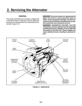
When dealing with intricate machinery, it’s crucial to have a clear representation of how each element interacts within the overall mechanism. Visual layouts of mechanical assemblies offer an insightful way to grasp the roles of different elements, aiding in both troubleshooting and maintenance tasks. In such systems, precision and clarity are key to ensuring smooth operation and longevity.
By examining technical blueprints, one can identify key elements that are essential to the operation of these systems. Each component serves a specific function, and understanding their relationship helps not only in performing repairs but also in optimizing the performance of the entire setup. Whether you’re conducting routine upkeep or more complex adjustments, a clear reference to the structure is invaluable.
Overview of the Onan Marquis 7000 System
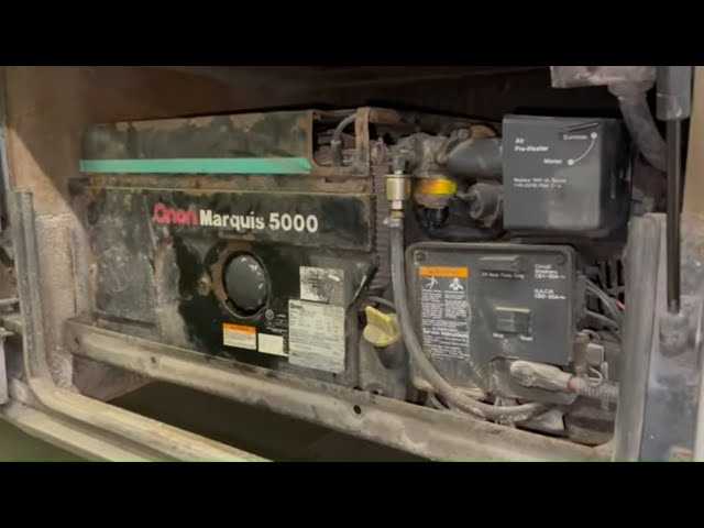
This advanced engine-driven setup offers a reliable solution for powering various electrical devices. Designed for consistent performance, it provides the user with a dependable source of energy, even in demanding situations. The system is optimized to handle multiple tasks while maintaining efficient operation, making it ideal for applications requiring continuous power generation.
Key Features
- Highly efficient design for reduced fuel consumption
- Quiet operation with noise-dampening technology
- Automatic control mechanisms for ease of use
- Durable construction to withstand various environmental conditions
Operational Benefits
- Long runtime with minimal maintenance
- Enhanced safety features for user protection
- Compatibility with a wide range of electrical setups
Key Components and Their Functions
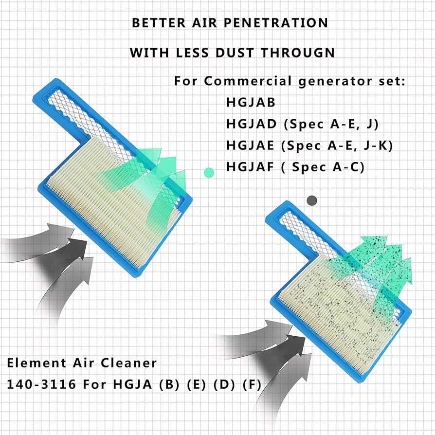
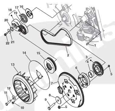
This section provides an overview of the essential elements that ensure the system operates smoothly. Understanding the roles of these individual parts is crucial for efficient maintenance and troubleshooting. Each component plays a specific role in the overall functionality, contributing to the system’s reliability and performance.
Main Structural Elements
- Engine Unit: The heart of the system, responsible for generating the necessary energy to drive other components.
- Cooling Mechanism: Ensures the engine maintains optimal temperature, preventing overheating during operation.
- Exhaust System: Safely removes combustion gases, ensuring smooth and safe performance over extended periods.
Electrical and Control Systems
- Voltage Regulator: Monitors and adjusts the electrical output to maintain consistent performance levels.
- Control Panel: The interface that allows users to monitor and adjust operational parameters as needed.
- Starter Motor: Initiates the system’s operation, ensuring a smooth and reliable start-up process.
Detailed Breakdown of Engine Elements
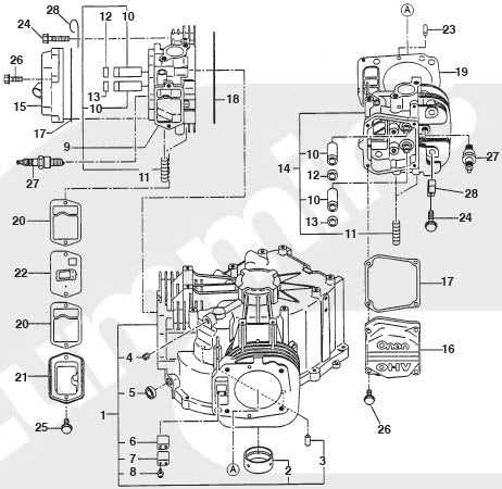
The engine in question is a complex system, composed of various interdependent components. Each part plays a critical role in ensuring smooth operation and optimal performance. In this section, we will explore the core mechanisms and how they function together to maintain the efficiency of the entire system.
| Component | Function |
|---|---|
| Cylinder Block | The foundation of the engine, housing critical components such as pistons and crankshaft. |
| Pistons | Responsible for converting fuel combustion into mechanical motion, driving the system forward. |
| Crankshaft | Transforms the linear motion of the pistons into rotational energy, powering the generator. |
| Valves | Regulate the flow of air and fuel into the engine, as well as the exhaust of gases. |
| Cooling System | Maintains optimal temperature to prevent overheating during operation. |
| Ignition System | Generates the spark necessary to ignite the air-fuel mixture, starting the engine cycle.
Understanding the Electrical System Structure
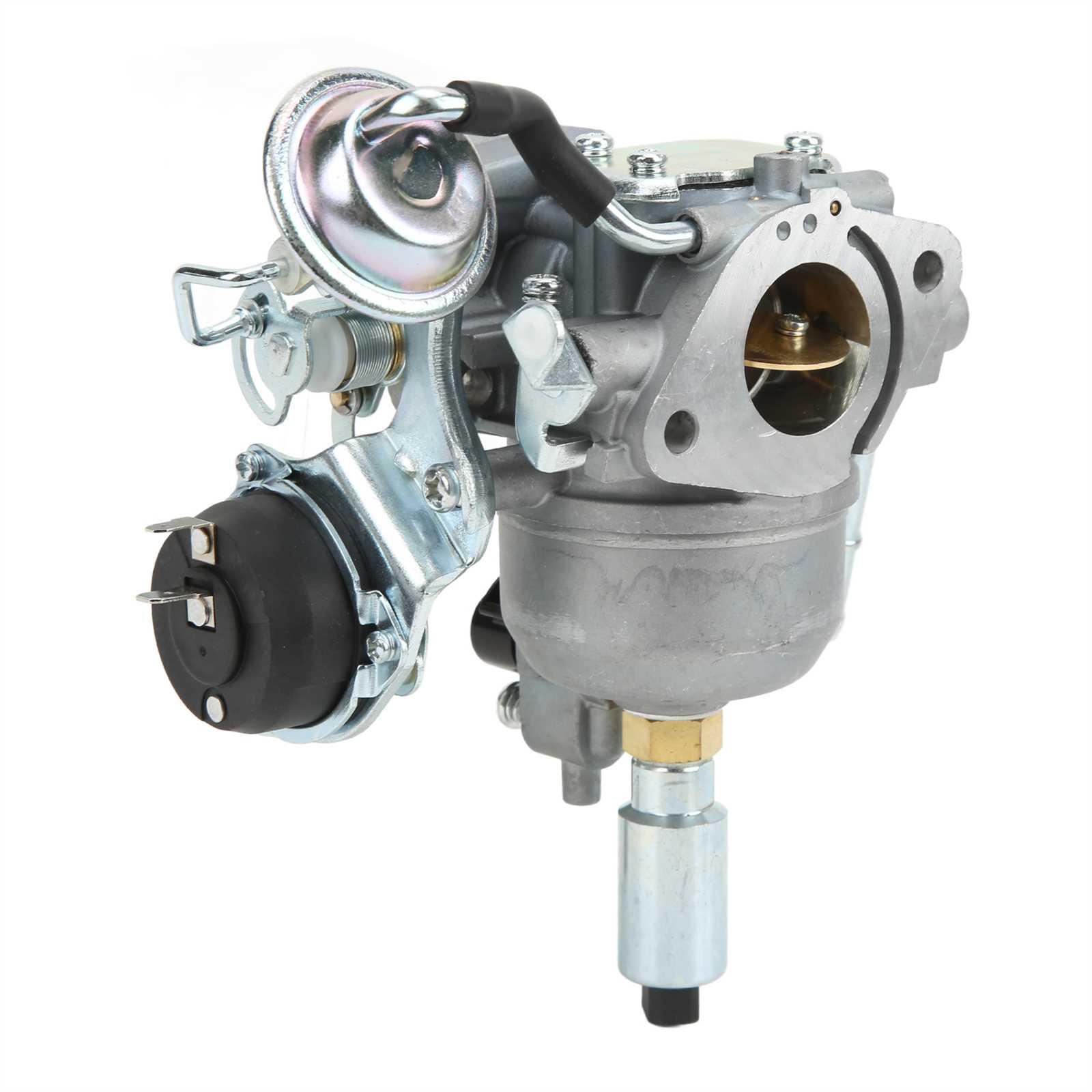
The electrical setup within any large mechanical device plays a pivotal role in its overall functionality. A well-organized network of wires, switches, and connectors ensures the efficient flow of current, powering critical components for smooth operation. Understanding this structure helps in diagnosing issues and maintaining the system effectively. Key elements of the setup typically include a central distribution point, multiple circuits for different functions, and safety mechanisms to prevent overload. Each section has its own distinct role, ensuring stability and control over the power flow across various mechanical and electronic parts. Critical connections such as fuses and relays act as safeguards, while control panels and sensors manage operational performance. By familiarizing oneself with these core elements, it becomes easier to handle repairs, upgrades, or routine inspections without facing unnecessary complications. Fuel System Layout and ConnectionsThe configuration of the fuel supply is essential for ensuring smooth operation and optimal performance. Understanding how different elements work together allows for easier maintenance and troubleshooting. This section explores the key aspects of the setup, providing an overview of the components involved and their functional interactions. Fuel lines are carefully routed to minimize potential obstructions and ensure an efficient flow. Each connection is designed to maintain a secure and tight seal, preventing leaks that could disrupt the system’s efficiency. Along with the lines, filters play a critical role in safeguarding the system from impurities, ensuring that only clean fuel reaches the main components. The pump is another key element, responsible for moving the fuel from the tank to the operational areas. It operates in tandem with control mechanisms that regulate flow based on demand. The entire system is engineered to balance pressure and maintain consistent delivery, supporting the equipment’s functionality even under varying load conditions. Exhaust Mechanism and Ventilation Parts
The efficiency of any engine is significantly influenced by its exhaust system and ventilation components. These elements work together to ensure proper gas expulsion and optimal airflow, which are crucial for maintaining performance and safety. Understanding the design and functionality of these components can greatly enhance the overall operation of the machinery. At the core of the exhaust mechanism lies the manifold, which collects gases from the engine and directs them towards the outlet. Coupled with the manifold are gaskets that create a tight seal, preventing any leaks that could diminish efficiency. Following this, the muffler plays a vital role in reducing noise levels while allowing for smooth gas passage. Ventilation is equally important, as it ensures that fresh air circulates through the engine, aiding in combustion. The intake system facilitates this airflow, while filters work to remove impurities, safeguarding the internal components. Proper maintenance of these systems is essential to avoid overheating and to extend the lifespan of the engine. In conclusion, understanding the intricacies of the exhaust and ventilation systems not only improves performance but also enhances the overall reliability of the equipment. Regular inspection and timely replacements of these crucial components are recommended to ensure optimal functionality. Cooling System Parts and Operation
The efficiency and longevity of any generator depend significantly on its thermal management. Proper cooling is essential to prevent overheating and ensure optimal performance. Understanding the components involved in this system helps in maintenance and troubleshooting, leading to a more reliable operation. Key Components
Operational OverviewThe cooling mechanism functions by circulating a mixture of water and antifreeze through the engine and radiator. As the engine operates, it generates heat, which the coolant absorbs. This heated fluid then travels to the radiator, where it releases heat to the surrounding air, aided by the cooling fan. The cooled liquid returns to the engine, creating a continuous loop that prevents overheating. Regular inspection and maintenance of these components are vital to ensure the system operates effectively. This includes checking for leaks, ensuring proper fluid levels, and verifying the functionality of the thermostat and water pump. By maintaining these elements, the generator can operate efficiently and extend its service life. Control Panel and User Interface DetailsThe control interface serves as the primary interaction point for users, facilitating easy management and monitoring of the system’s operations. Understanding the layout and functionality of this interface is crucial for effective usage and maintenance. This panel typically features an array of buttons, dials, and indicators that provide essential information regarding operational status and allow users to make adjustments as necessary. Each component is designed to enhance user experience, ensuring that information is clearly displayed and easily accessible. Among the key elements are the power switch, status lights, and control knobs. The power switch enables the user to start or stop the system, while status lights indicate the operational state, such as readiness or fault conditions. Control knobs allow for adjustments in settings, granting users the ability to tailor performance to their specific needs. Overall, a well-designed control panel ensures intuitive navigation, empowering users to manage their equipment effectively and safely. Maintenance Tips for Key Parts Replacement
Regular upkeep of essential components is vital for ensuring optimal functionality and longevity of your equipment. By following specific guidelines for part replacements, you can enhance performance and reduce the risk of breakdowns. Here are some practical suggestions to help you through the process. 1. Schedule Regular InspectionsConducting frequent evaluations allows you to identify wear and tear early. Establish a routine check-up schedule to inspect critical components.
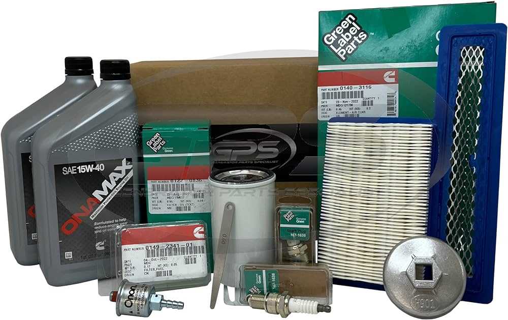
2. Use Quality Replacement ComponentsSelecting high-quality replacements is essential for maintaining performance. Always consider the following:
Implementing these strategies will facilitate effective management of your equipment and ensure that it operates efficiently for years to come. |
