Understanding the intricacies of mechanical equipment involves recognizing the arrangement and interaction of various elements. Each element plays a role in ensuring smooth operation and efficiency, contributing to the overall functionality of the machinery. This knowledge helps in maintaining and adjusting the equipment, ensuring it operates at its best.
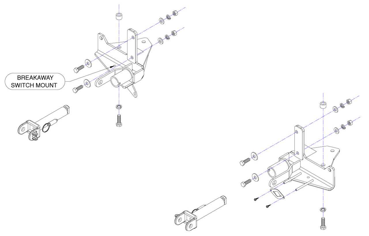
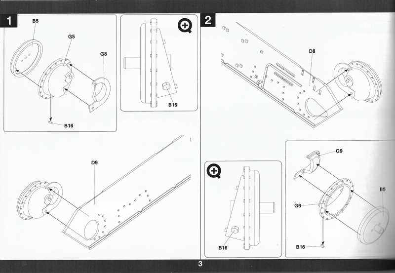
Detailed schematics are invaluable for those looking to gain a deeper understanding of how each element integrates into the whole. These visual guides highlight the connections and relationships between different parts, making it easier to identify key areas for adjustment and maintenance.
Familiarity with the arrangement of essential components ensures that adjustments can be made with precision, leading to enhanced performance. These insights aid in troubleshooting, allowing users to identify potential issues and address them efficiently.
Kuhn GMD 700 GII HD Overview
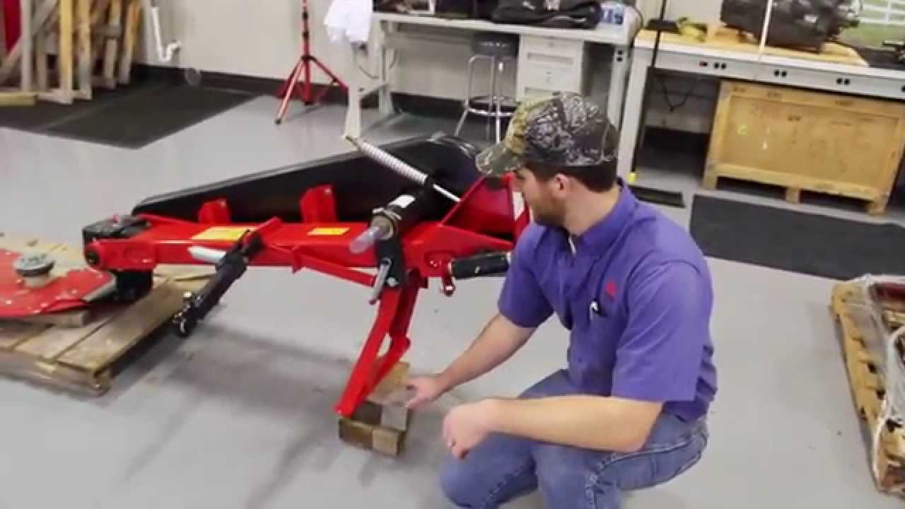
This agricultural tool is designed for efficient fieldwork, offering robust construction and high performance. Engineered for a range of terrain, it ensures durability and optimal functionality, making it a preferred choice for large-scale operations. Its innovative design aids in maintaining consistency, even under demanding conditions.
The equipment boasts advanced features that enhance its cutting precision and overall efficiency. With a focus on reliability, it supports smooth operation, reducing the need for frequent maintenance. This makes it an ideal solution for those looking to maximize productivity while minimizing downtime.
Built with the user in mind, this machine combines strength with ease of use. The structural elements are thoughtfully arranged to provide balance, enabling seamless handling during various tasks. Its design prioritizes both safety and performance, ensuring long-term use in a variety of working environments.
Main Features and Specifications
This section explores the key attributes and technical details of the equipment, highlighting its essential qualities and functionality. It provides an overview of what makes this machine suitable for various operational needs and demands, emphasizing its strengths and adaptability.
Key Functionalities
The machine is designed to deliver optimal performance in a variety of conditions. It is built for durability and ease of use, ensuring that it meets the requirements of both novice and experienced operators. The design incorporates advanced mechanisms that support efficient operation, reducing time and effort needed during use.
Technical Specifications

| Feature | Detail |
|---|---|
| Cutting Width | Wide range for flexible operations |
| Build Material | Reinforced structure for extended longevity |
| Weight | Optimized for stability and ease of transport |
| Operating Mechanism | Enhanced for smooth and reliable performance |
Components and Their Functions
Understanding the various elements of a mechanical assembly is crucial for effective maintenance and repair. Each part plays a distinct role, contributing to the overall operation and efficiency of the machinery. Proper knowledge of these elements helps to ensure smooth functionality and prevents unexpected breakdowns.
Rotational Elements are vital for transmitting power throughout the system. These components convert energy into motion, allowing the equipment to perform its primary tasks efficiently. Regular inspection ensures that they remain in good working condition, reducing wear and tear.
Structural Supports provide the necessary stability, holding the different sections together. They are designed to withstand stress and distribute weight evenly, which is essential for the long-term durability of the system.
Connection Points play a key role in joining various parts, ensuring seamless interaction between moving and static sections. Maintaining these connectors is crucial to avoid disruptions in functionality and to facilitate easy adjustments when needed.
How to Identify Spare Parts

Understanding the specifics of different components can greatly simplify the maintenance process. Recognizing each piece by its shape, size, and placement is key to efficient upkeep and replacement. This guide will help to distinguish various elements for better organization and quicker identification during repairs.
Visual Examination Techniques
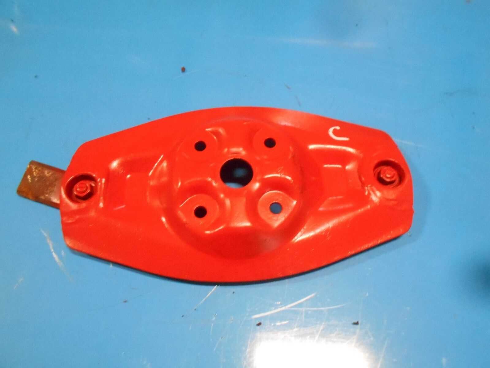
Start by closely observing the physical characteristics of each item. Look for unique markings, textures, or shapes that can serve as identifiers. These distinguishing features often reveal the function and proper placement of each component. Using a detailed reference can help to match the visual clues with the required element.
Using Reference Materials
Technical manuals and visual guides are valuable tools for identifying components accurately. These resources often contain detailed illustrations that highlight where each element belongs and how it interacts with others. Comparing the actual item with a reference image can ensure accurate selection during replacements or repairs.
Common Replacement Parts
Maintenance of agricultural equipment often requires replacing worn or damaged components to ensure optimal performance. Regular upkeep helps to extend the lifespan of various machinery and keep them operating smoothly during intensive work periods. Below is a list of frequently exchanged elements that are crucial for maintaining functionality.
| Component | Description | Maintenance Tip |
|---|---|---|
| Blades | Essential for cutting vegetation efficiently, these require sharpness and periodic checks for wear. | Inspect before each season and replace when dullness affects performance. |
| Bearing Kits | These provide smooth rotation for moving parts, reducing friction and preventing damage. | Lubricate regularly and replace if you notice unusual noise or resistance. |
| Belts | Responsible for transmitting power between different parts of the equipment, they are prone to stretching and cracking over time. | Check for tension and replace if signs of wear are visible. |
| Hydraulic Seals | Crucial for maintaining pressure in hydraulic systems, preventing fluid leaks. | Inspect for leaks regularly and replace if the seal shows signs of wear. |
| Skid Shoes | Protects the underside of the equipment from damage during operation on rough terrain. | Replace when excessive wear compromises the protective layer. |
Maintenance Tips for Optimal Performance
Ensuring the longevity and efficiency of agricultural machinery requires regular attention and care. By following essential upkeep practices, operators can significantly enhance the overall functionality and reliability of their equipment. This section outlines key strategies to maintain optimal performance and prevent common issues.
Regular Inspection
Routine checks are vital for identifying potential problems before they escalate. Consider the following points:
- Examine components for wear and tear.
- Check fluid levels, including oil and hydraulic fluids.
- Inspect belts and chains for proper tension and alignment.
Proper Cleaning

Keeping machinery clean is crucial for preventing damage and ensuring efficient operation. Follow these cleaning practices:
- Remove debris and residue after each use.
- Clean air filters regularly to maintain airflow.
- Use appropriate cleaners for different surfaces to avoid corrosion.
Troubleshooting Mechanical Issues
Identifying and resolving mechanical problems is essential for ensuring the optimal performance of agricultural equipment. By systematically diagnosing issues, operators can maintain efficiency and extend the lifespan of their machinery.
Common Mechanical Problems
Several typical issues may arise during operation, including:
- Unusual noises: Grinding or squeaking sounds can indicate wear or misalignment.
- Vibrations: Excessive vibrations often signal loose components or imbalance.
- Inconsistent performance: Fluctuating operation can stem from mechanical faults or blockages.
Steps for Effective Troubleshooting

To effectively address mechanical challenges, follow these steps:
- Perform a thorough visual inspection of the machinery.
- Check for any loose or damaged parts.
- Consult the maintenance manual for specific guidance.
- Test operational components systematically to isolate the issue.
By adopting a methodical approach, users can identify and rectify problems promptly, ensuring the reliable functionality of their equipment.
Installation of New Parts
Replacing components in machinery is essential for maintaining optimal performance and functionality. This section outlines the procedures for installing new elements effectively, ensuring longevity and reliability in operations.
Before commencing the installation process, it is crucial to gather all necessary tools and components. Following the correct steps can minimize errors and enhance efficiency.
Preparation Steps
- Ensure the machinery is powered down and securely locked to prevent accidental operation.
- Collect the required tools, including wrenches, screwdrivers, and any specialized equipment needed for the task.
- Review the installation instructions provided with the new components to familiarize yourself with the process.
Installation Process
- Remove the old components carefully, ensuring no damage to surrounding parts.
- Clean the area where the new elements will be installed to remove any debris or residues.
- Position the new components accurately, aligning them with existing fixtures.
- Secure the new parts using the appropriate fasteners, ensuring they are tightened to the specified torque.
- Perform a visual inspection to confirm that everything is in place and correctly assembled.
Following these guidelines will help ensure a smooth installation process, promoting the effective functioning of your equipment.
Understanding the Diagram Layout
This section aims to elucidate the arrangement of visual representations used in machinery documentation. The layout is crucial for comprehending the relationship between various components and their functions within a system. A clear understanding of the structure can enhance maintenance efficiency and troubleshooting processes.
Key Elements of the Layout
Each visual representation typically includes several essential elements:
- Component Labels: Each part is often labeled with identifiers that help in recognizing their functions.
- Connection Lines: Lines that illustrate how different elements are interconnected, indicating flow paths or functional relationships.
- Legend or Key: A reference guide explaining symbols or color codes used throughout the representation.
Interpreting Relationships
Understanding how to interpret the connections between components is vital for effective analysis. Here are some tips for interpreting these relationships:
- Follow the Flow: Track how processes move through the system to identify critical paths.
- Look for Groupings: Components often grouped together serve related functions, making it easier to diagnose issues.
- Use the Legend: Always refer to the key for clarification on symbols and color meanings.