
Understanding the inner workings of a machine can be greatly enhanced by exploring its detailed layout. A visual representation of the various elements that make up the machinery provides valuable insight into its functionality and structure. This helps in identifying how different sections work together and ensures smoother maintenance or repair operations.
By examining a clear breakdown of the internal mechanisms, technicians and users alike can develop a deeper knowledge of how the individual sections interact. This knowledge is essential for anyone looking to optimize performance or troubleshoot specific issues in a mechanical system.
Having access to a well-organized map of the essential components makes it easier to carry out necessary adjustments, ensuring the longevity and reliability of the equipment. Such clarity allows for better decisions when it comes to replacements or upgrades, keeping the machine running efficiently.
Key Components Overview

This section provides a detailed look at the essential components of a versatile power unit designed for welding and generator functions. Understanding the main elements is crucial for effective operation and maintenance, ensuring longevity and reliable performance in demanding environments.
Power Generation Unit
- Engine: Responsible for generating the necessary energy, typically powered by gas or diesel.
- Generator: Converts mechanical energy from the engine into electrical output for welding and auxiliary power.
- Cooling System: Ensures the engine and generator remain at optimal temperature during prolonged use.
Welding and Control System
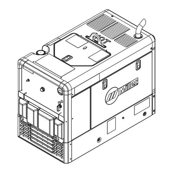
- Welding Output Terminals: The connection points for welding cables, providing necessary power for various welding processes.
- Control Panel: Features various controls, including amperage settings, voltage adjustments, and diagnostic indicators.
- Safety Mechanisms: Built-in safety features such as overload protection and automatic shutdown to prevent damage and accidents.
Understanding the Engine Parts Layout
The layout of the engine components is essential for ensuring proper maintenance and repair. Each part is interconnected, working together to deliver optimal performance. Understanding how these components are arranged will help identify potential issues and streamline servicing.
Main Engine Components
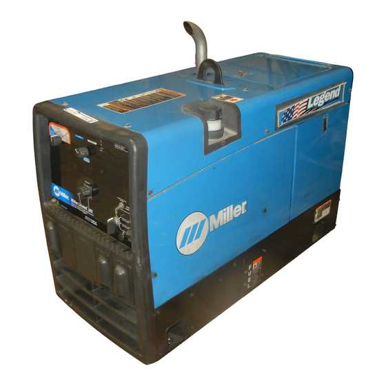
- Cooling system: Regulates the engine’s temperature, preventing overheating.
- Fuel system: Supplies the necessary fuel for combustion.
- Exhaust system: Removes gases generated during the combustion process.
- Ignition system: Ensures the engine starts and runs efficiently.
Component Connections
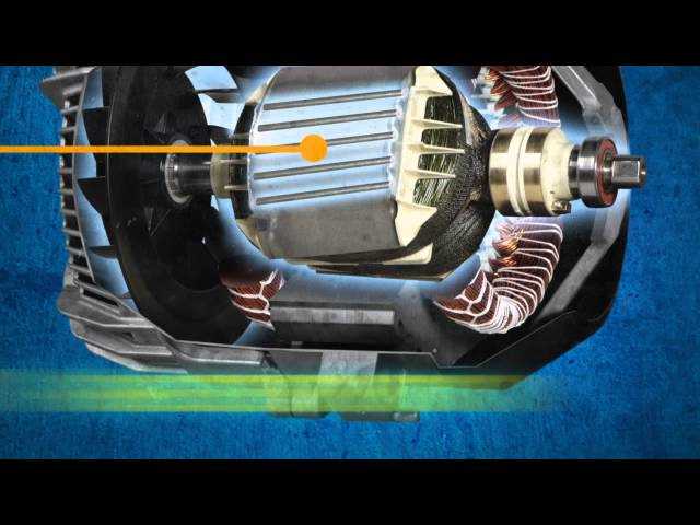
- The fuel injectors are linked to the combustion chamber to provide fuel efficiently.
- The cooling system connects to various sensors that monitor engine temperature.
- The exhaust manifold is attached to the engine block, expelling exhaust gases safely.
Electrical System Components and Their Placement
Understanding the layout and positioning of the key elements in the electrical system is essential for efficient maintenance and troubleshooting. Each component has a specific role within the system, contributing to its overall functionality and ensuring stable operation.
Main Components
- Battery: Provides the initial power required to start and maintain operations.
- Alternator: Generates electricity to power equipment and recharge the battery during use.
- Voltage Regulator: Ensures a consistent voltage level is maintained throughout the system.
Component Placement
- Control Panel: Typically located on the front, providing access to switches and indicators.
- Wiring Harness: Routes electrical connections between different parts, ensuring efficient power distribution.
- Grounding Points: Found in various locations to ensure safety and prevent electrical faults.
Fuel System Parts and Diagram Explanation
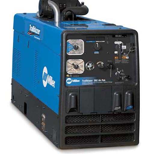
The fuel system ensures the proper delivery of fuel from the tank to the engine, maintaining optimal performance. This section will outline the essential components involved in this process and their roles in keeping the machine running smoothly.
Fuel Tank: This is the reservoir where fuel is stored before being sent to the engine. It must be secure and free from leaks to ensure proper operation.
Fuel Lines: These tubes transport the fuel from the tank to the engine. Their durability and proper installation are crucial to avoid interruptions in the fuel flow.
Fuel Pump: The pump generates pressure that pushes the fuel through the system, ensuring a consistent flow to the engine. If it malfunctions, the fuel delivery can be compromised, leading to performance issues.
Fuel Filter: This component cleans the fuel before it reaches the engine, removing debris and contaminants. A clogged filter can hinder fuel flow and reduce engine efficiency.
Each of these elements plays a critical role in the system, and any issues with these parts can affect the overall performance of the engine. Ensuring they are maintained and functioning properly is vital for optimal operation.
Cooling System Components: Diagram Breakdown
The cooling system plays a crucial role in maintaining the optimal temperature of the machine during operation. It ensures that heat generated by the engine or other internal components is efficiently dissipated, preventing overheating and ensuring smooth performance. In this section, we will explore the key elements involved in the cooling process and how they interact with each other.
| Component | Function | |||||||||||
|---|---|---|---|---|---|---|---|---|---|---|---|---|
| Radiator | Transfers heat from the coolant to the air, helping to reduce engine temperature. | |||||||||||
| Thermostat | Regulates the flow of coolant based on the engine’s temperature, ensuring optimal performance. | |||||||||||
| Water Pump | Circulates coolant through the engine and radiator, maintaining a consistent flow for heat management. | |||||||||||
| Cooling Fans |
| Component | Description |
|---|---|
| Exhaust Manifold | Collects exhaust gases from multiple cylinders and channels them to the exhaust pipe. |
| Catalytic Converter | Reduces harmful emissions by converting toxic gases into less harmful substances. |
| Muffler | Reduces noise produced by the exhaust gases as they exit the system. |
| Exhaust Pipe | Transfers exhaust gases from the manifold through the system to the outside atmosphere. |
| Gaskets | Seals connections between various components to prevent leaks of exhaust gases. |
Starter Assembly: Parts and Functions
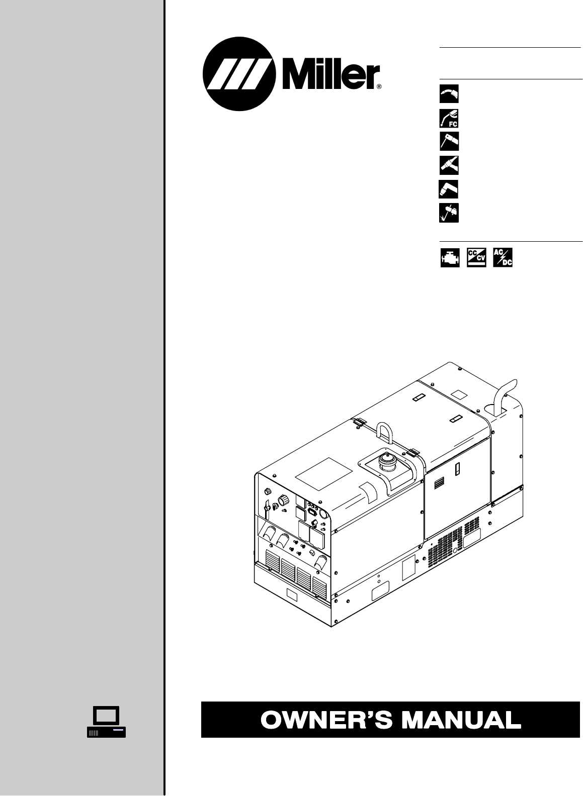
The starter assembly is a crucial component of any machinery, serving to initiate the engine’s operation. Understanding its various elements and their roles can enhance maintenance and troubleshooting efficiency.
Key Components
- Starter Motor: The primary device responsible for turning the engine over to begin combustion.
- Solenoid: An electromagnetic switch that engages the starter motor when the ignition is activated.
- Battery: Provides the electrical energy needed to power the starter motor and solenoid.
- Starter Relay: Facilitates the high-current flow from the battery to the starter motor, allowing for effective operation.
- Flywheel: Engages with the starter pinion to transmit torque and crank the engine.
Functions of Each Element
- Starter Motor: Converts electrical energy into mechanical energy, rotating the flywheel.
- Solenoid: Connects the battery to the starter motor, initiating the starting process.
- Battery: Supplies the necessary voltage and current to kickstart the motor and solenoid.
- Starter Relay: Protects the ignition switch and circuits by handling high current safely.
- Flywheel: Provides a surface for the starter pinion to engage, enabling the engine to start.
Understanding the Wiring and Circuit Layout
Grasping the intricacies of electrical connections and circuit arrangements is crucial for efficient operation and maintenance. A thorough understanding aids in troubleshooting and optimizing the functionality of equipment.
The wiring system typically consists of various components, each serving specific roles within the circuit. Recognizing these elements is essential for anyone working with electrical setups.
- Power Sources: These are the initial points supplying energy to the system.
- Conductors: Wires and cables facilitating the flow of electricity between components.
- Control Devices: Switches and relays that manage the flow of current based on operational requirements.
- Load Devices: Components such as motors or lights that utilize electrical energy for functionality.
When examining the overall layout, it is important to consider the following aspects:
- Connection Points: Identifying where different components link can clarify circuit behavior.
- Voltage Ratings: Understanding the voltage levels required for each component helps prevent damage.
- Safety Protocols: Implementing proper safety measures is vital when working with electrical systems.
By familiarizing oneself with the wiring and circuit layout, operators can enhance their troubleshooting skills, leading to more effective maintenance and repairs.
Maintenance Tips Based on Parts Diagram
Regular upkeep is essential for ensuring the longevity and efficient operation of your equipment. Understanding the components involved allows for more effective maintenance strategies, helping to prevent common issues and enhance overall performance. By following specific guidelines based on the configuration of individual parts, users can extend the lifespan of their machinery and optimize functionality.
Routine Inspection and Cleaning
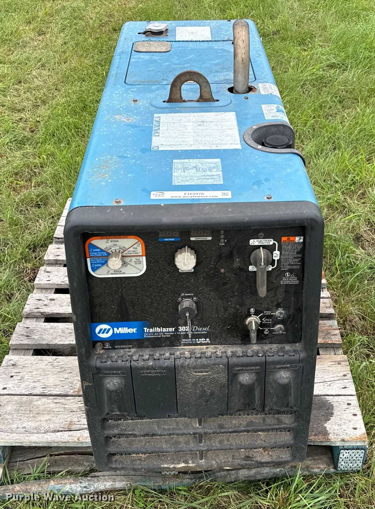
Regular inspections are crucial for identifying wear and tear before they escalate into significant problems. Check all components regularly for signs of damage or degradation. Additionally, cleaning the parts to remove debris and contaminants can significantly improve performance and reduce the risk of failure.
Lubrication and Fluid Levels
Ensuring that all moving elements are adequately lubricated is vital for smooth operation. Check fluid levels frequently and replace them according to the manufacturer’s recommendations. Proper lubrication reduces friction and wear, contributing to a longer lifespan of the equipment.