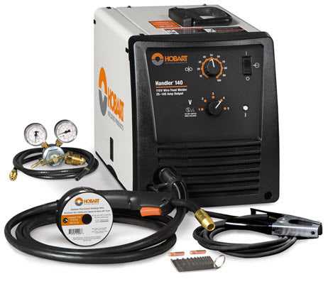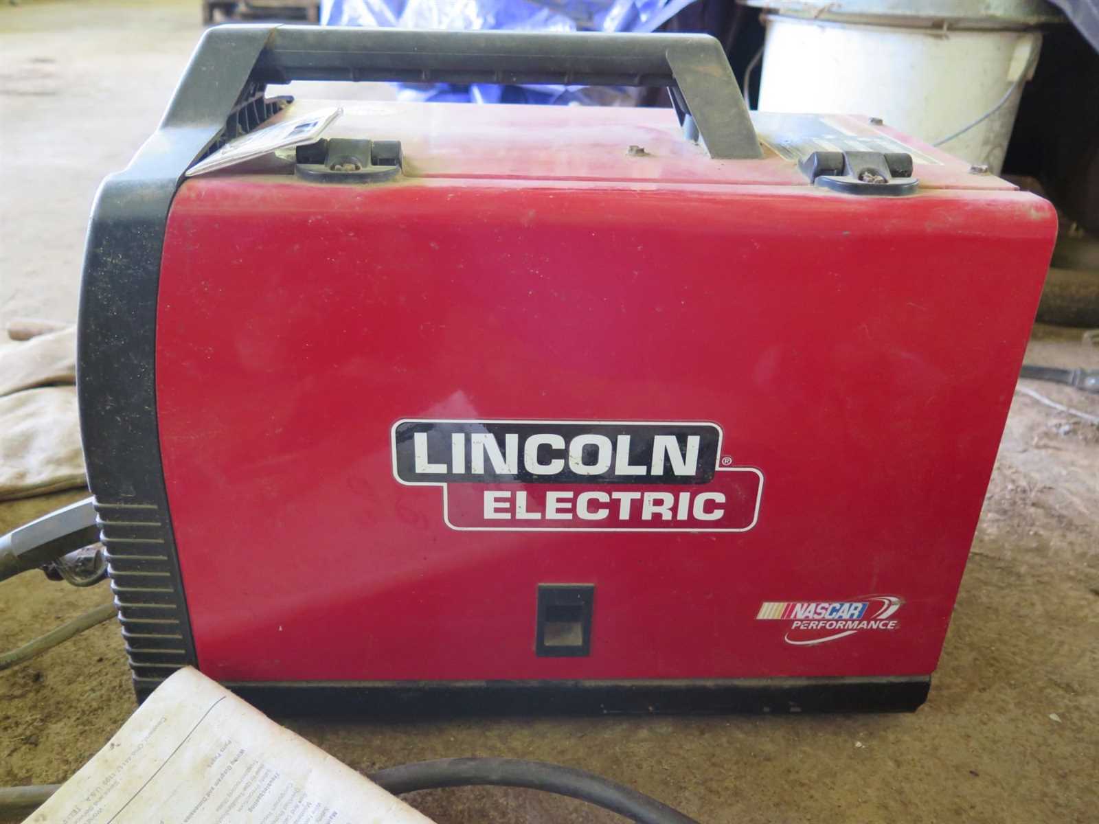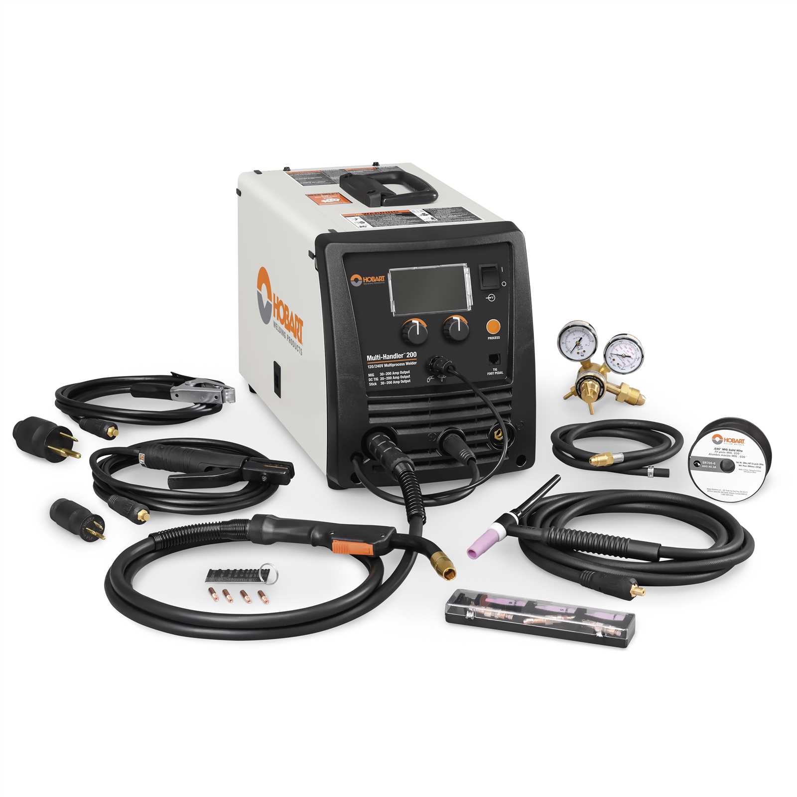
The functionality of heavy-duty equipment often relies on understanding its internal components and how they interact. Visual guides and breakdowns of intricate assemblies can assist technicians and operators in maintaining efficiency and ensuring smooth operations. Having a clear representation of various elements within mechanical systems is essential for both troubleshooting and routine maintenance.
Understanding the arrangement of various mechanical and electrical elements within industrial devices can help prevent issues before they arise. Knowing how each part connects and functions in relation to others allows for quick identification of wear or potential malfunctions, ensuring the longevity and reliability of the equipment.
To ensure optimal performance, it’s important to familiarize oneself with the internal setup, which can vary depending on the specific model and configuration. By following detailed layouts and understanding the role of each element, users can confidently approach maintenance tasks with precision.
Lincoln 140 MIG Welder Parts Diagram
The equipment’s internal layout consists of multiple interconnected components designed to work together efficiently. Each section plays a crucial role in ensuring smooth operation, from the core power supply unit to the wire feed mechanism and beyond. Understanding this layout helps users troubleshoot issues and maintain their device effectively. By analyzing the positioning of each component, one can gain insights into how the different elements interact and contribute to the overall functionality.
The primary sections are organized in a logical manner, allowing easy access for maintenance and repairs. The electrical circuits, protective housings, and cooling systems are strategically positioned to ensure maximum efficiency. Recognizing the relationships between these elements simplifies both troubleshooting and routine inspections, making it easier for operators to ensure optimal performance over time.
Main Components of the Welding Machine
Welding equipment is composed of several essential elements that work together to enable the joining of metals. These components ensure the effective operation of the system and provide users with control over the welding process. Understanding these elements helps in maintenance and proper usage.
Core Electrical Units
- Power Source: Provides the necessary electrical current for the process. It ensures a stable flow of electricity.
- Wire Feeder: Delivers a continuous wire to the working area, maintaining consistency during operation.
- Control Panel: Allows the operator to adjust parameters such as voltage and wire speed for optimal performance.
Mechanical and Safety Features
- Gun Assembly: This includes the handle, trigger, and nozzle, guiding the wire and gas during the procedure.
- Casing and Cooling System: Ensures the machine does not overheat and protects internal parts from damage.
Internal Wiring and Circuitry Layout

The internal wiring and circuitry arrangement plays a crucial role in ensuring efficient electrical distribution and performance. Properly designed connections between components guarantee reliable operation and minimize the risk of short circuits or system failures. Understanding the layout helps to identify key areas for maintenance or upgrades.
Main Components Overview
The main elements of the internal circuitry include various control boards, power connections, and safety mechanisms. Each component is carefully interconnected to maintain functionality and protect the system from electrical overload.
- Control boards: Direct current to the appropriate systems.
- Power connections: Ensure smooth energy transfer.
- Safety mechanisms: Prevent overloads and protect the system.
Wiring Structure
The wiring structure consists of several key pathways that link different sections of the machine. These include connections to the power source, control systems, and external output units.
- Power input wiring: Delivers electricity from the power supply.
- Control wiring: Directs signals for system regulation.
-
Gas Regulator and Hose Assembly
The gas regulator and hose assembly is a critical component for ensuring a smooth and efficient gas flow during metalworking tasks. This assembly helps to manage and control the flow of shielding gases, which play a key role in protecting the workspace from contamination. Proper setup and maintenance of this system are essential for achieving optimal performance and consistent results.
Main Functions of the Gas Regulator
- Controls the pressure and flow rate of the shielding gas.
- Ensures a stable output to maintain the desired atmosphere during operation.
- Protects against sudden pressure surges that could affect accuracy and safety.
Hose Installation and Maintenance Tips
- Ensure all connections are secure and free from leaks before starting work.
- Regularly check for wear or cracks in the hose to prevent gas loss or malfunction.
- Store the hose in a coiled position to avoid unnecessary stress on the material.
Drive Rollers and Wire Feed System
The drive rollers and wire feed system play a crucial role in ensuring smooth and consistent feeding of the wire through the machine. These components work together to guide the wire from the spool, maintaining the right tension and preventing any interruptions in the feeding process. Properly aligned and maintained rollers help avoid issues like wire slipping or jamming, which can affect performance.
Regular inspection of the drive rollers is essential to ensure they are free of debris and wear. Over time, worn rollers can reduce efficiency, leading to poor wire feeding. Adjusting the tension on the wire feed system is also important to match the wire diameter and type, ensuring optimal operation.
In summary, the drive rollers and wire feed system are key elements that directly influence the precision and reliability of the welding process. Maintaining these parts in good condition enhances overall performance and reduces downtime.
Power Supply and Transformer Details
The power supply unit plays a crucial role in the functionality of welding equipment, ensuring that the necessary voltage and current are provided for optimal performance. A well-designed transformer is integral to converting and regulating electrical energy, facilitating the welding process effectively and safely.
Functionality of the Power Supply
The power supply is responsible for delivering consistent energy to the device, enabling stable arc formation. It converts the incoming voltage from the outlet to a suitable level for welding operations, ensuring that the required amperage is maintained throughout the task. This reliability is vital for achieving quality welds and preventing damage to the equipment.
Transformer Characteristics

Transformers in welding equipment are engineered to step down or step up voltage levels, depending on the application. They are typically constructed with durable materials to withstand high temperatures and electrical stresses. The efficiency of a transformer directly influences the performance of the welding apparatus, affecting factors such as heat output and energy consumption.
Torch and Nozzle Structure Overview
The functionality of a welding apparatus relies significantly on the intricate design of its torch and nozzle components. These elements are essential for delivering the welding wire and shielding gas, ensuring a controlled and precise operation during the welding process.
Key Components of the Torch
The torch is typically composed of several critical parts that work together seamlessly. A main body houses the electrode, while the trigger mechanism allows the operator to control the flow of the welding wire. This combination enables smooth feeding, ensuring that the welding process remains consistent and efficient.
Understanding the Nozzle Design
The nozzle serves a vital role in directing the shielding gas around the welding arc. Its design affects the gas flow and the heat distribution, which are crucial for achieving optimal welding results. A well-structured nozzle not only protects the weld pool but also contributes to the overall quality and integrity of the finished weld.
Control Panel Functions and Layout
The control interface of a welding machine serves as the central hub for managing various operational parameters and settings. Understanding its arrangement and functions is essential for effective usage and maintenance. This section outlines the primary components and their roles in ensuring optimal performance during welding tasks.
Typically, the interface features several key elements, including knobs, switches, and digital displays. Each component is designed to adjust specific parameters such as voltage, wire feed speed, and operational modes. The layout is often organized intuitively, allowing users to easily access and modify settings while focusing on their welding work.
For enhanced usability, some panels may incorporate indicator lights or meters that provide real-time feedback on performance metrics. Familiarity with these visual cues can help users diagnose issues quickly and maintain proper functionality. Overall, an efficient control panel is crucial for achieving consistent and high-quality welds.
Replacement Parts and Maintenance Tips
Ensuring the longevity and efficiency of your equipment requires regular attention and appropriate component replacements. Familiarity with the essential elements can aid in timely interventions, preventing larger issues down the line.
When seeking substitutes, it is crucial to choose components that match the specifications of the original setup. Using compatible replacements not only guarantees optimal functionality but also enhances performance. Regular checks on frequently worn items, such as nozzles and contact tips, can help maintain a seamless operation.
Additionally, establishing a maintenance routine can significantly prolong the lifespan of your equipment. This includes cleaning the internal systems and ensuring proper ventilation to prevent overheating. Implementing these practices will lead to improved efficiency and reduced downtime.