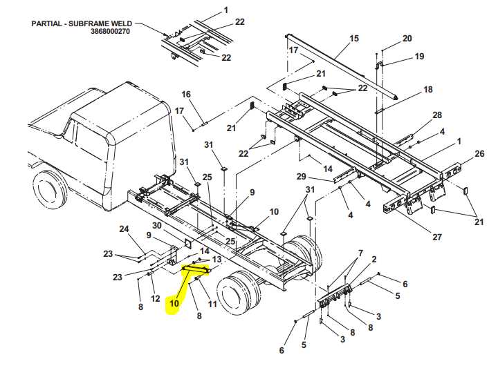
In the realm of towing machinery, a comprehensive grasp of the individual components is crucial for optimal functionality. Each element plays a pivotal role in ensuring seamless operation and reliability, making it essential for operators and technicians alike to familiarize themselves with these intricate systems.
Exploring the assembly of these mechanical elements provides insight into their respective functions and interconnections. This knowledge not only aids in maintenance but also enhances troubleshooting capabilities, allowing for prompt identification of issues and ensuring that the equipment remains in peak condition.
By delving into the specifics of the various components, users can better appreciate the engineering behind the apparatus. This understanding fosters improved handling, safety, and efficiency, ultimately contributing to a more effective towing experience.
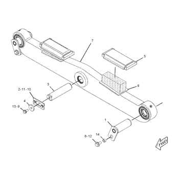
The functionality of specialized recovery mechanisms relies on several essential elements. These components work in harmony to ensure that the equipment operates effectively and meets the demands of various towing situations. Understanding these key aspects is crucial for proper maintenance and optimal performance.
Main Elements of the System
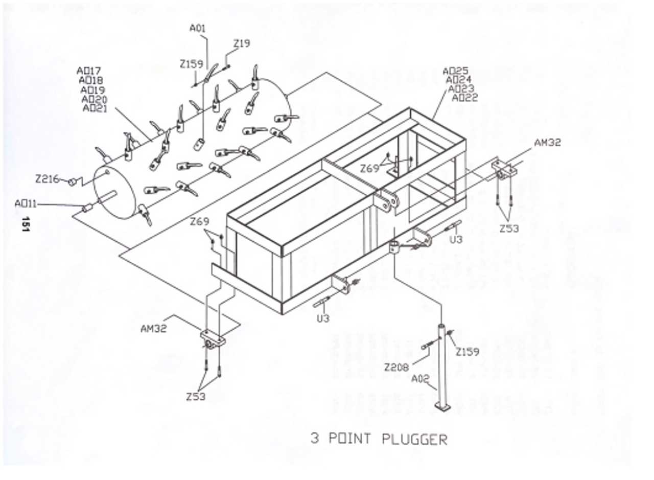
- Hydraulic System: This crucial mechanism allows for the movement and positioning of the apparatus, enabling it to engage with vehicles securely.
- Frame Structure: A robust frame provides stability and support, ensuring that the entire system can withstand heavy loads during operations.
- Control Unit: The interface for operators to manage the various functions of the system, enhancing user experience and safety.
Additional Functional Parts
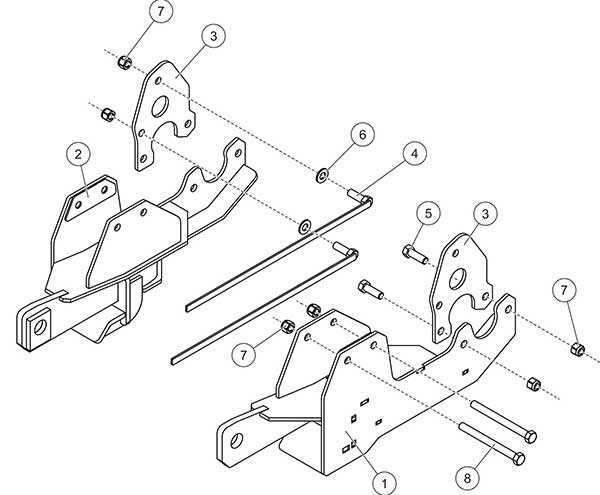
- Winch Assembly: Essential for pulling vehicles, this component is designed for strength and reliability.
- Safety Features: Built-in systems to prevent accidents, ensuring that operations are conducted safely.
- Lighting Components: Important for visibility during nighttime or low-light conditions, improving safety for both operators and vehicles.
Understanding Hydraulic Mechanisms
Hydraulic systems utilize fluid power to perform various tasks, transforming energy into mechanical movement. These mechanisms operate on the principle of incompressibility of liquids, allowing for efficient force transmission over distances. By harnessing the pressure exerted by hydraulic fluid, these systems can generate significant lifting and pushing capabilities, making them essential in various applications.
At the core of hydraulic operations is the hydraulic cylinder, which converts hydraulic energy into linear motion. The design typically consists of a cylinder, piston, and sealing elements. The flow of fluid is controlled by valves, ensuring precise movement and operation. Understanding the components and functionality of these systems is crucial for effective maintenance and operation.
| Component | Description |
|---|---|
| Hydraulic Fluid | Transmits power and lubricates components. |
| Pump | Generates flow by converting mechanical energy into hydraulic energy. |
| Actuator | Converts hydraulic energy into mechanical motion. |
| Valves | Control the flow and direction of the hydraulic fluid. |
| Reservoir | Stores hydraulic fluid and allows for heat dissipation. |
Hydraulic mechanisms are integral to modern machinery, offering efficiency and power in various industrial and automotive applications. A thorough understanding of these systems enhances oper
Maintenance Tips for Wheel Lifts
Proper upkeep of towing equipment is essential for ensuring optimal performance and longevity. Regular attention to maintenance routines not only enhances safety but also minimizes the risk of unexpected failures during operation. Here are some effective strategies to keep your apparatus in top condition.
Regular Inspections
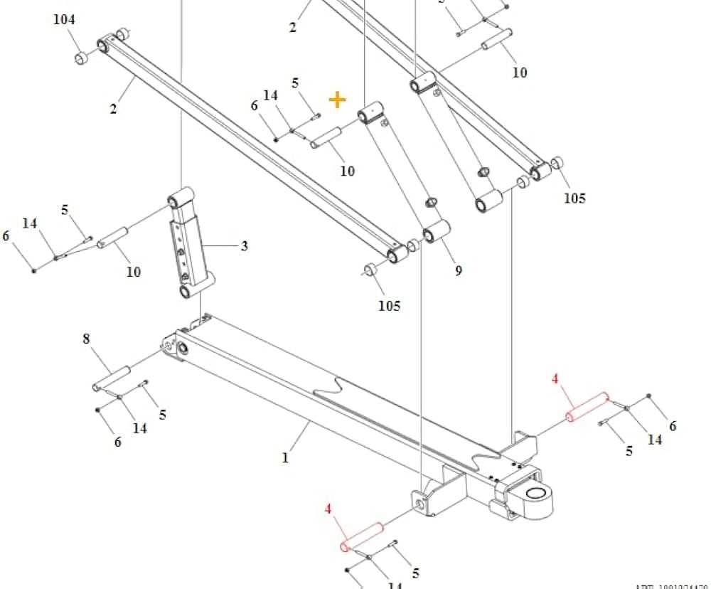
Conducting frequent checks is crucial. Examine all components for signs of wear, corrosion, or damage. Pay special attention to hydraulic systems, as leaks can lead to significant issues if not addressed promptly. Ensure that all connections are secure and free from obstructions.
Lubrication and Cleaning
Keep moving parts adequately lubricated to prevent friction and wear. Use high-quality lubricants recommended by manufacturers. Additionally, clean the equipment regularly to remove dirt and debris that can affect functionality. A well-maintained surface enhances the overall performance and appearance of the gear.
Common Issues and Solutions
When operating lifting equipment, users may encounter various challenges that can hinder performance and efficiency. Recognizing these common problems and understanding their solutions can significantly enhance the operational lifespan and reliability of the system.
- Inconsistent Functionality:
This can occur due to electrical malfunctions or inadequate power supply. Regularly check connections and ensure that the power source meets the required specifications.
- Hydraulic Leaks:
Leaks can lead to reduced lifting capacity and pose safety risks. Inspect hoses and fittings regularly, and replace any worn or damaged components promptly.
- Excessive Wear on Components:
Over time, various elements may show signs of wear. Routine maintenance, including lubrication and component replacement, can prevent further damage.
- Unresponsive Controls:
If the controls are unresponsive, it may be due to wiring issues or faulty control units. Conduct a thorough inspection of the wiring and replace any defective parts.
- Noise During Operation:
Unexpected noises can indicate mechanical issues. Identify the source of the noise and consult a technician for a proper diagnosis and repair.
Addressing these issues promptly can ensure safe and efficient operation, minimizing downtime and extending the lifespan of the equipment.
How to Read Parts Diagrams
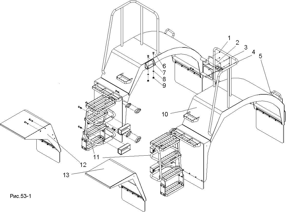
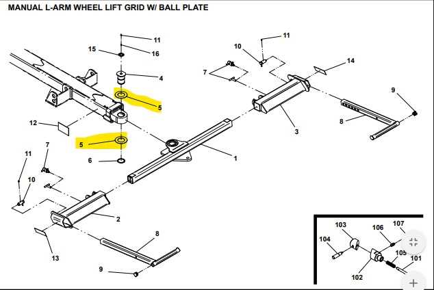
Understanding technical illustrations is essential for anyone involved in the maintenance and repair of machinery. These visuals provide a detailed representation of components and their arrangement, helping users identify the necessary elements for efficient assembly or repair tasks.
To begin interpreting these visuals, focus on the key symbols and notations that indicate different parts. Each element typically corresponds to a specific component, and the accompanying labels clarify their functions and relationships. Familiarizing yourself with these symbols is crucial for effective comprehension.
Additionally, pay attention to the orientation and layout of the illustration. This can offer insights into how the components interact with one another, highlighting potential assembly sequences. Always consult the accompanying documentation, as it often contains invaluable information regarding specifications and compatibility.
Lastly, practice is vital. The more you work with these illustrations, the more adept you’ll become at quickly identifying components and understanding their roles within the system. Embrace the learning process, and soon you will navigate technical visuals with confidence.
Replacement Parts and Upgrades
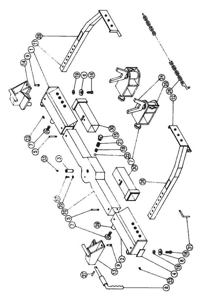
Ensuring optimal performance and reliability of your equipment involves considering various components that may need to be updated or replaced over time. Upgrading certain elements can significantly enhance functionality, extend the lifespan of the system, and improve overall efficiency. This section highlights essential components that may require attention for maintenance and improvement.
| Component | Description | Benefits of Replacement/Upgrade |
|---|---|---|
| Hydraulic Pump | Essential for generating the necessary pressure for operation. | Increased lifting capacity and improved speed. |
| Control Valves | Regulates fluid flow and direction within the system. | Smoother operation and enhanced responsiveness. |
| Hoses and Fittings | Connects various components, allowing fluid transfer. | Reduces risk of leaks and increases system reliability. |
| Wiring Harness | Facilitates electrical connections between parts. | Improved safety and reduced electrical failures. |
| Wear Plates | Protects against abrasion and extends component life. | Minimized wear and prolonged durability of critical parts. |
Safety Features in Wheel Lifts
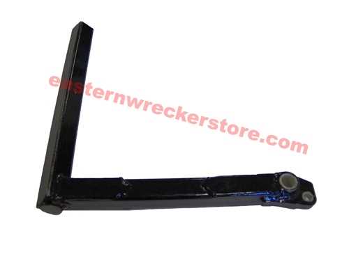
Ensuring the protection of both operators and vehicles is crucial in any lifting operation. Advanced safety mechanisms play a vital role in reducing the risks associated with heavy-duty towing and transportation tasks. These features are designed to provide a secure environment, enhancing efficiency and peace of mind during usage.
Key Safety Mechanisms
- Automatic Load Monitoring: Systems that continuously check the weight being lifted, preventing overload situations.
- Stability Sensors: Sensors that detect shifts in weight distribution, ensuring the structure remains balanced.
- Emergency Shutoff: Quick-access switches that halt operations immediately in case of an emergency.
- Reflective Markings: High-visibility decals that enhance visibility during low-light conditions.
Operator Training and Guidelines
Proper training is essential for maximizing safety during operations. Operators should be well-versed in the features and functions of the equipment. Adhering to established guidelines and performing regular inspections can significantly reduce accidents and ensure optimal performance.
- Complete safety training before operating the equipment.
- Conduct daily checks for any signs of wear or damage.
- Always follow manufacturer instructions and safety guidelines.