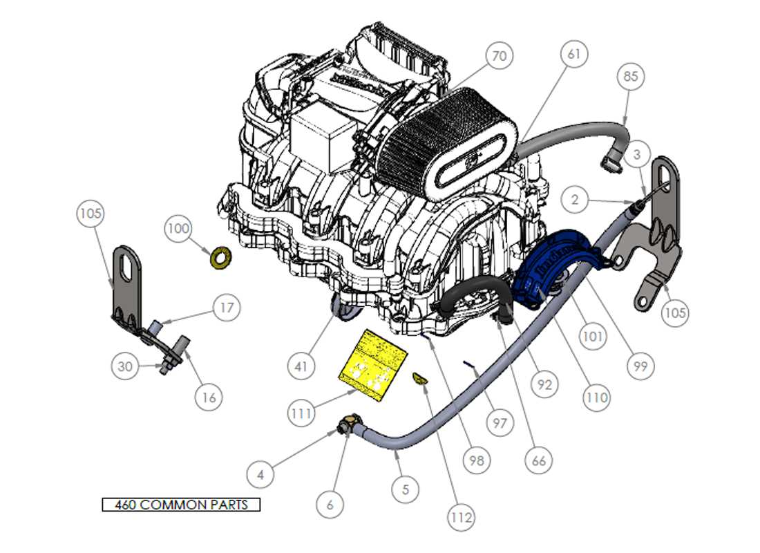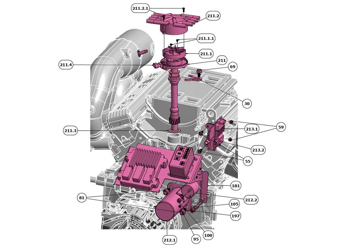
Understanding the intricate design and layout of mechanical systems is essential for maintaining optimal performance. In this section, we explore the key elements of a well-known engine setup, highlighting their interconnections and functions. By gaining insights into the various aspects of this engine, you will better grasp how each element contributes to the overall operation, ensuring efficiency and reliability.
Each component plays a crucial role in the overall system. We will provide a detailed look at the essential parts, focusing on their placement and interaction with other elements. This guide will assist in recognizing the most vital elements for troubleshooting and maintenance purposes.
Whether you are maintaining or upgrading your engine, a clear understanding of the essential components and their relationships can significantly enhance your knowledge. Let’s delve into the structure and gain a deeper comprehension of how each part works in harmony within the engine’s system.
Overview of the Indmar 5.7 Engine Components
The engine in question is designed to deliver reliable performance, with each part working in harmony to ensure efficient operation. This section will provide a detailed look at the major elements that make up the system, exploring their functions and interconnections. From the core components responsible for power generation to the supportive elements that maintain stability, every piece plays a vital role in the overall functionality.
Main Power Generation Units
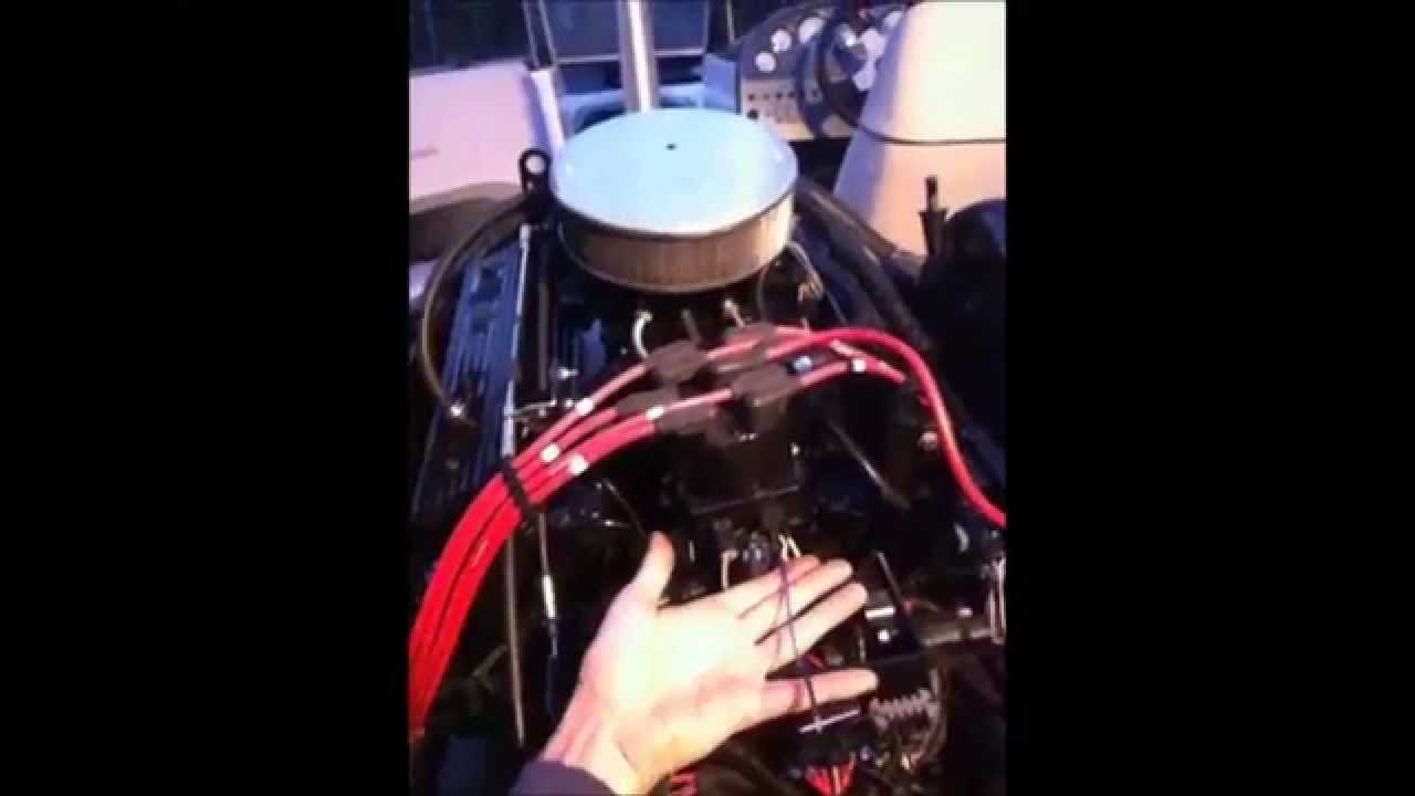
At the heart of the engine lies the system responsible for converting fuel into mechanical energy. Key elements here include the combustion chamber, pistons, and crankshaft. Together, these components drive the power output that propels the machinery forward, ensuring smooth and consistent operation even under demanding conditions.
Supportive Systems
In addition to the main power units, several auxiliary systems are critical for maintaining balance and performance. These include the cooling system, which prevents overheating, and the fuel injection system, ensuring proper fuel delivery. Other vital elements include the lubrication system and exhaust system, both of which contribute to the overall efficiency and longevity.
| Component | Function |
|---|---|
| Combustion Chamber | Location where fuel is ignited to generate power
Key Features and Specifications of the Indmar 5.7
This section explores the core characteristics and technical aspects of a popular marine engine, highlighting its performance, durability, and other essential components. By examining these features, we can better understand what makes this engine a reliable choice for various watercraft applications. Performance and Efficiency
Durability and Maintenance
Main Systems in the Indmar 5.7 Engine
Each motorized unit relies on a set of interconnected mechanisms that ensure efficient operation. These components work together to regulate various functions, from fuel combustion to exhaust management, all contributing to optimal performance. Fuel Delivery System: The engine’s fuel system is responsible for providing a consistent flow of fuel to the cylinders. This system ensures proper fuel-air mixture, enabling efficient combustion and power generation. Cooling Mechanism: A vital aspect of any engine’s functionality is its ability to maintain an optimal temperature. The cooling mechanism circulates coolant, preventing overheating and ensuring long-term reliability. Exhaust System: After the fuel is burned, the exhaust system handles the expulsion of gases. This process ensures that harmful emissions are filtered, reducing environmental impact and improving overall engine efficiency. Ignition Setup: The ignition system controls the timing and delivery of sparks to ignite the fuel-air mixture in the cylinders, a critical function for maintaining smooth and responsive power output. Lubrication Circuit Understanding Core Functional AreasThe effective operation of any mechanical system relies on several fundamental components that work in harmony. Each segment plays a vital role, ensuring the entire unit functions smoothly and efficiently. Understanding these essential areas is crucial for anyone looking to maintain or enhance the performance of the machinery. Key Components of the System
Importance of Each AreaEach functional area is interconnected, and the performance of one affects the others. For instance, if the power generation unit fails, it impacts the entire system’s ability to operate. Regular maintenance and understanding the intricacies of these components can lead to improved efficiency and longevity.
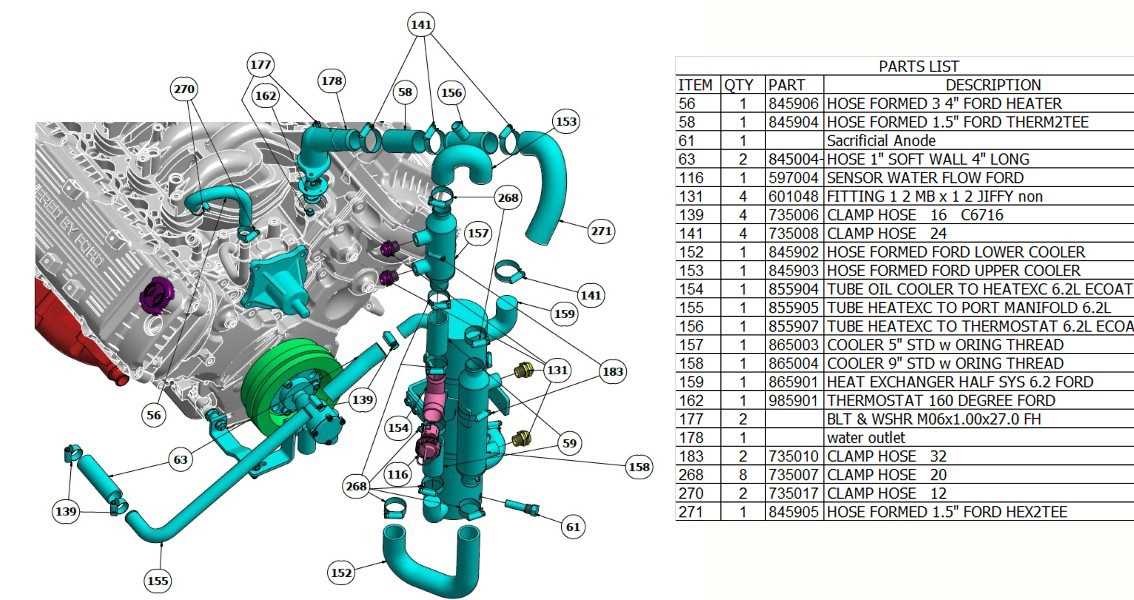
Cooling System Parts and FunctionThe cooling mechanism in an engine plays a crucial role in maintaining optimal operational temperatures, ensuring efficient performance and longevity. This system comprises various components that work together to dissipate excess heat generated during combustion and mechanical activities. Radiator: This vital element is responsible for transferring heat away from the engine coolant. As the fluid flows through the radiator, air passes over the fins, facilitating heat exchange and cooling the liquid before it circulates back into the engine. Water Pump: This component circulates the coolant throughout the engine and the radiator. By maintaining proper fluid movement, the water pump ensures that the engine remains at a stable temperature, preventing overheating. Thermostat: This device regulates the coolant flow based on temperature. When the engine reaches a predetermined heat level, the thermostat opens, allowing the coolant to flow into the radiator for cooling. Conversely, it closes when the temperature drops, ensuring the engine warms up efficiently. Coolant Hoses: These flexible tubes connect various parts of the cooling system, transporting the coolant to and from the engine, radiator, and other components. Their integrity is crucial for preventing leaks and ensuring effective fluid circulation. Expansion Tank: This reservoir accommodates fluctuations in coolant volume due to temperature changes. As the coolant heats up and expands, it flows into the tank; when it cools, the fluid is drawn back into the system, maintaining consistent levels. Understanding these components and their functions highlights the importance of the cooling mechanism in maintaining engine health and efficiency. Regular maintenance and checks of these elements can significantly extend the lifespan of the engine and enhance performance. How the Cooling Mechanism WorksThe cooling system in a marine engine plays a crucial role in maintaining optimal operating temperatures. This mechanism ensures that the engine functions efficiently, preventing overheating and potential damage. By circulating coolant through various components, the system dissipates excess heat generated during operation. Typically, the cooling process involves several key elements:
Each component works in harmony to ensure that the engine remains within a safe temperature range. The effective management of heat is vital not only for performance but also for the longevity of the engine. Fuel Delivery Mechanism and ComponentsThe fuel delivery system is a crucial element of an engine, responsible for providing the necessary combustible mixture to ensure optimal performance. This mechanism encompasses various components that work in unison to transport fuel efficiently from the tank to the combustion chamber, enabling smooth operation and reliability. Key Components
Operation of the Delivery System
The fuel delivery process begins with the pump drawing fuel from the tank. Once the fuel is filtered, it travels through the fuel lines to the injectors. The injectors then atomize the fuel, mixing it with air before it enters the combustion chamber. Proper functioning of each component is vital to maintain engine efficiency and performance. Critical Elements of the Fuel SystemThe fuel delivery mechanism plays a vital role in the overall performance and efficiency of any combustion engine. A well-functioning system ensures that the right amount of fuel is supplied at the correct pressure, contributing to optimal engine operation. Understanding the critical components involved in this process is essential for maintenance and troubleshooting. Key ComponentsAmong the fundamental elements are the fuel tank, which stores the liquid until needed, and the fuel pump, responsible for transferring it to the engine. Additionally, the fuel filter serves to eliminate impurities, protecting the engine from damage and maintaining efficiency. Each of these parts must work harmoniously to achieve reliable performance. Importance of MaintenanceRegular inspection and upkeep of these components are crucial for preventing potential issues. Neglecting any part of the system can lead to fuel delivery problems, resulting in reduced power output or even engine failure. By ensuring that each element is functioning correctly, one can prolong the life of the engine and enhance overall performance. Exhaust System Design and Operation
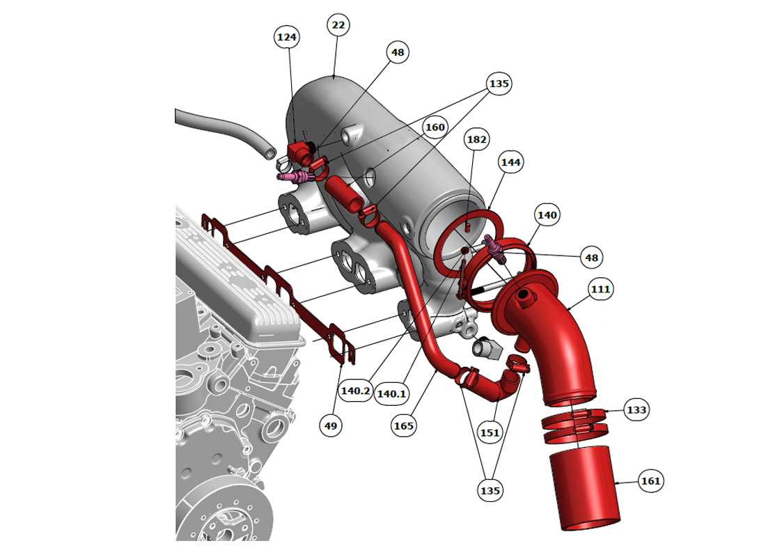
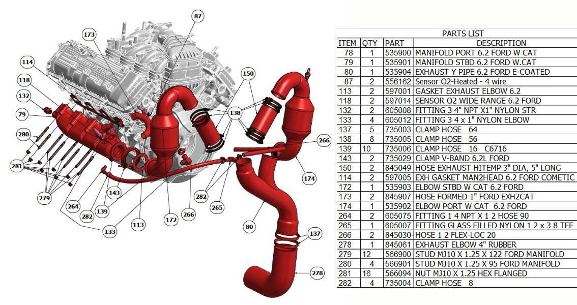
The exhaust system is a critical component in the overall functionality of an engine, responsible for directing harmful gases away from the combustion chamber. This system plays a vital role in maintaining optimal performance and efficiency while ensuring compliance with environmental regulations. Understanding its design and operation is essential for effective maintenance and troubleshooting. The layout of the exhaust system typically includes several key elements, such as the manifold, catalytic converter, and muffler. Each part serves a specific purpose, contributing to the overall effectiveness of gas expulsion. The manifold collects gases from the cylinders and channels them into the exhaust pipe, while the catalytic converter reduces harmful emissions. Finally, the muffler minimizes noise generated by the escaping gases. Efficient operation of the exhaust system relies on proper airflow and pressure management. Restrictions in these areas can lead to performance issues, such as reduced power output and increased fuel consumption. Regular inspections and maintenance help identify potential blockages or leaks that may hinder functionality. Overall, a well-designed exhaust system not only enhances engine performance but also plays a significant role in environmental sustainability. Understanding its components and their functions is crucial for anyone involved in engine maintenance or repair. Key Parts Ensuring Optimal Exhaust FlowEfficient exhaust flow is essential for maximizing engine performance and maintaining optimal operating conditions. Various components play crucial roles in facilitating this process, ensuring that gases are expelled effectively and efficiently, which helps to enhance overall efficiency and reduce emissions. Critical Components
Factors Influencing Performance
|
