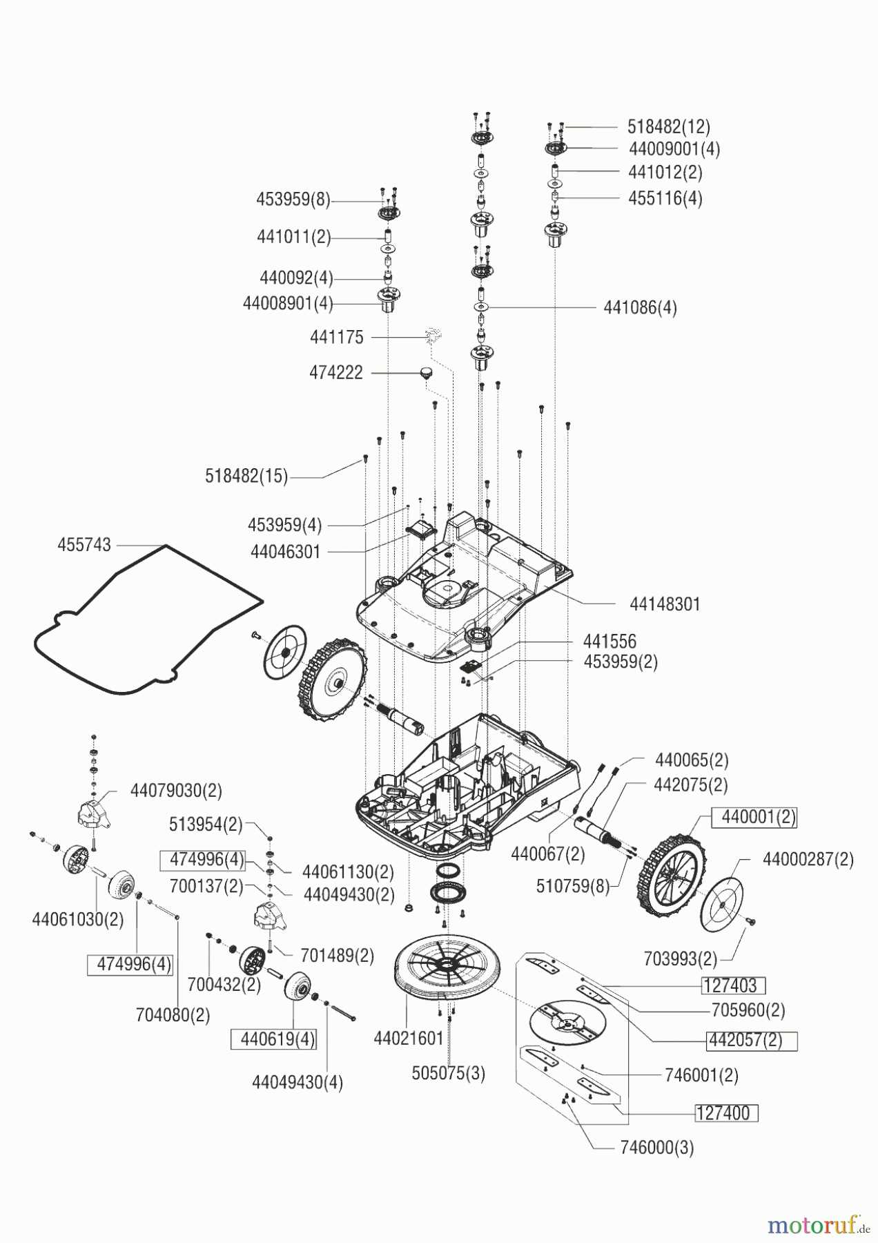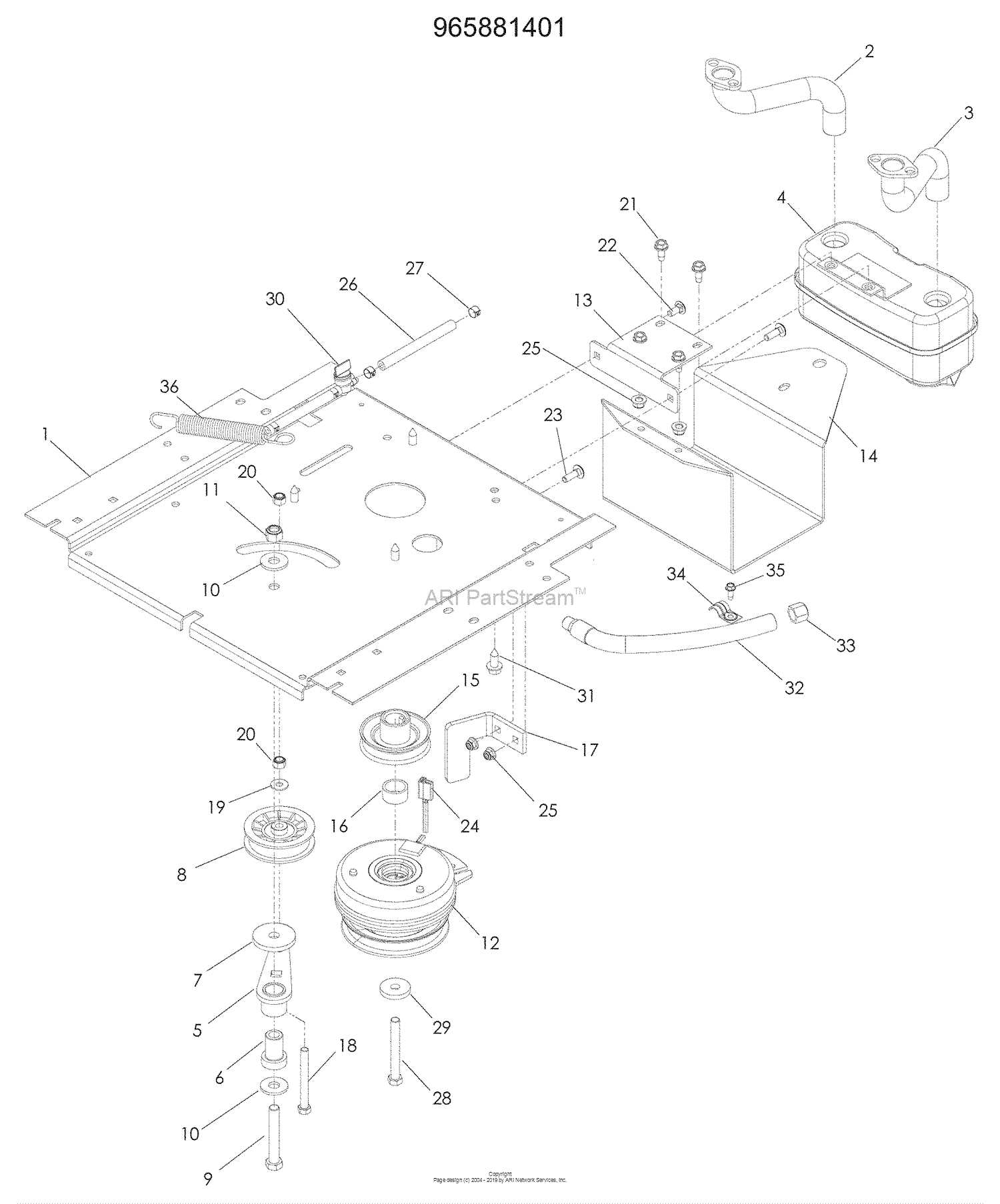
Maintaining a reliable and well-functioning machine requires a solid grasp of its core elements. Knowing how each part contributes to the overall operation can significantly enhance performance and longevity. This section delves into the structural arrangement of essential elements, offering a clear view of how various components interact. By understanding these connections, owners and technicians can approach repairs and regular maintenance with greater confidence.
Each mechanism within a high-performance system serves a specific role, working in sync with others to ensure seamless operation. Identifying the configuration of these elements not only aids in targeted repairs but also in routine inspections, helping prevent potential issues before they arise. Here, you’ll find an organized outline of each section, offering insights into its role, connection points, and position within the overall framework.
For those looking to enhance efficiency and keep their equipment in peak condition, a detailed examination of the setup can be invaluable. Knowing the precise arrangement empowers users to quickly assess, replace, or repair individual elements as needed. This structured guide serves as a practical reference, laying the groundwork for optimized upkeep and hassle-free operation.
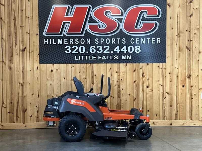
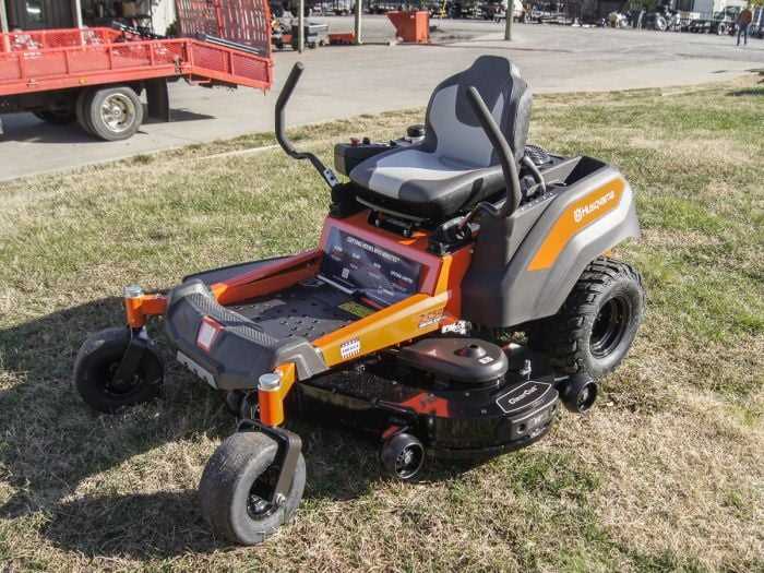
Comprehensive Guide to Husqvarna Z254F Components
This section provides a detailed overview of the essential elements and features integral to this machine’s effective operation. Understanding each element’s role ensures proper maintenance and troubleshooting, maximizing efficiency and lifespan.
| Component | Description | Function |
|---|---|---|
| Engine | High-performance core with a robust design. | Powers the machine, delivering the necessary strength for various terrains. |
| Drive System | Advanced mechanism that controls movement. | Facilitates forward and reverse motion with variable speed control. |
| Cutting Deck | Durable structure designed to withstand rough conditions. | Houses blades that ensure an even and precise trim. |
| Blade Assembly | Sharp, high-quality cutting components. | Responsible for effective grass cutting and leveling. |
| Control Panel | User interface for easy operation. | Allows the operator to manage
Engine and Power System Overview
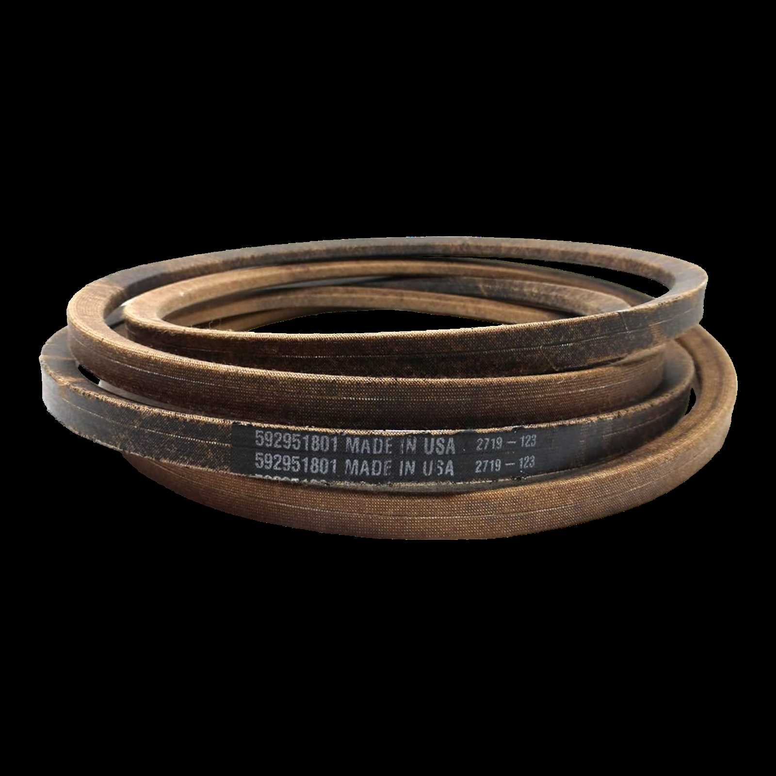
The engine and power system are the driving force behind the operation, providing the necessary energy to ensure efficient performance across various terrains and tasks. Designed to offer reliability and strength, these components work in harmony to support consistent speed, control, and handling. Engine Structure and Performance The engine structure is crafted to maximize fuel efficiency while delivering substantial power output. By utilizing advanced engineering, it maintains steady performance under a range of conditions. Its design also supports smoother operation and minimizes fuel consumption, making it ideal for extended use. Fuel System and Power Output The fuel system is essential for regulating power output, offering stable energy flow to the machine. Its well-designed components contribute to optimized fuel delivery, which helps in sustaining powerful and consistent performance. This system, paired with a robust engine, enables reliable operation even during demanding tasks. Cooling and Maintenance Features A cooling mechanism ensures that the engine remains within a safe temperature range, preventing overheating and reducing the risk of wear. Maintenance features, such as accessible service points, are built into the power system, enabling easier upkeep and longer-lasting efficiency. Understanding the Cutting Deck AssemblyThe cutting deck is a key component in any lawn care machine, responsible for efficiently trimming grass to a desired length. This section will explore the layout and individual parts within the deck system, offering insights into how each element contributes to achieving a clean, precise cut. By understanding this structure, operators can maintain and troubleshoot the assembly with greater ease. Main Components of the DeckThe deck assembly features several essential elements, each with a unique role. Key parts include blades, spindles, and a belt system. The blades perform the actual cutting, rotating at high speed to slice through grass, while the spindles support the blades and facilitate their movement. The belt connects the engine to the blades, driving them to spin and cut efficiently. Each part must be correctly aligned and maintained to ensure consistent performance. Regular Maintenance for Optimal PerformanceProper upkeep of the deck is essential to extend its lifespan and maintain its cutting precision. Regularly inspecting and cleaning the blades prevents buildup that could hinder their movement. Checking the belt and spindle alignment also helps prevent issues related to vibration or uneven cuts. By performing routine maintenance, users can ensure that the deck operates smoothly, resulting in a well-kept lawn. Key Features of the Drive Mechanism
The drive system is essential for efficient motion and power transmission, providing the machine with the capability to navigate various terrains with precision and control. Its design is structured to ensure both speed and stability, adapting seamlessly to operator inputs for a smooth operational experience. Let’s explore the key components and functions that contribute to the reliability of this drive mechanism. Enhanced Power Transmission
At the heart of the drive mechanism is a robust transmission setup that optimizes power delivery. This structure allows for consistent motion across diverse conditions, balancing force with efficiency to handle a wide range of tasks. The carefully engineered parts work in tandem, minimizing friction and enhancing overall performance for a more durable system. Precision Control and ManeuverabilityOne of the standout aspects of this drive system is its exceptional control, enabling precise maneuverability even in tight spaces. Designed to respond effectively to directional shifts, the mechanism provides stability on slopes and varied surfaces. Quick response and smooth transitions make it particularly adept at navigating intricate paths, which is essential for complex tasks. Detailed View of Safety ComponentsIn any machine designed for outdoor tasks, safety components play an essential role in ensuring a secure and controlled operation. This section delves into the core safety mechanisms that protect both the operator and the machine during use. Understanding the layout and purpose of these features helps in maintaining peak safety levels and efficient handling. Main Safety Features
Additional Protective Elements
Regular inspection and understanding of these features enhance operational safety and contribute to a longer lifespan for the equipment. Keeping each part in optimal condition not Maintenance Essentials for Electrical PartsKeeping electrical elements in top condition ensures smooth and safe equipment operation over time. Regular upkeep can prevent unexpected breakdowns, reduce repair costs, and extend the component’s lifespan. Here are some critical practices for effectively managing these crucial elements. Inspection and CleaningRegular inspection is key to spotting issues before they become significant problems. Dust, debris, and moisture can affect performance, so it’s essential to keep these elements clean and dry. A simple routine can include:
Securing Connections and Replacing Worn Components
Loose connections and worn components can impact functionality and lead to larger issues if not addressed promptly. To maintain stability:
By following these basic maintenance guidelines, you help ensure the durability and reliability of each component, enhancing overall safety and effectiveness. Exploring the Blade and Clutch System
The blade and clutch system is essential for efficient grass cutting and smooth operation in lawn care equipment. This mechanism not only enables the rotation of cutting edges but also allows operators to control when these edges engage or disengage, enhancing both functionality and safety.
By understanding and maintaining each part of this system, operators can achieve more reliable results and extend the lifespan of their equipment, ensuring optimal performance over time. Fuel System Components and Operation
The fuel system is a crucial aspect of small engine operation, ensuring that the combustion process is efficient and effective. Understanding the various elements involved in this system helps to maintain optimal performance and reliability. Key components work together to deliver the correct amount of fuel to the engine, allowing it to operate smoothly under various conditions. Here are the primary elements of the fuel system:
Each of these components plays a vital role in the overall functionality of the fuel system. Proper maintenance and understanding of their operation can lead to improved performance and longevity of the engine. Tips for Replacing Worn-Out PartsReplacing components that have reached the end of their lifespan is essential for maintaining the functionality and efficiency of your equipment. This process not only enhances performance but also prolongs the overall lifespan of the machine. Understanding the right approach can significantly impact the success of your repairs. 1. Identify the Problematic Component: Before you begin the replacement process, carefully assess the machine to pinpoint the specific component that requires attention. Look for signs of wear, such as cracks, breaks, or excessive rust, which may indicate that a replacement is necessary. 2. Gather the Necessary Tools: Ensure you have all the required tools at hand before starting the replacement. Common tools may include wrenches, screwdrivers, and pliers. Having everything prepared will streamline the process and reduce the risk of errors. 3. Follow Manufacturer Guidelines: Refer to the manufacturer’s instructions for guidance on the correct procedures for replacing components. Adhering to these guidelines ensures that the replacement is performed safely and effectively, minimizing the risk of further issues. 4. Test the Equipment After Replacement: Once you have installed the new component, conduct a thorough test of the machine to confirm that it is operating smoothly. Listen for any unusual sounds and observe its performance to ensure everything is functioning as intended. 5. Maintain Regular Check-ups: After replacing the worn-out part, implement a routine maintenance schedule to monitor the condition of the remaining components. Regular inspections can help catch potential problems early, preventing the need for future replacements. |
