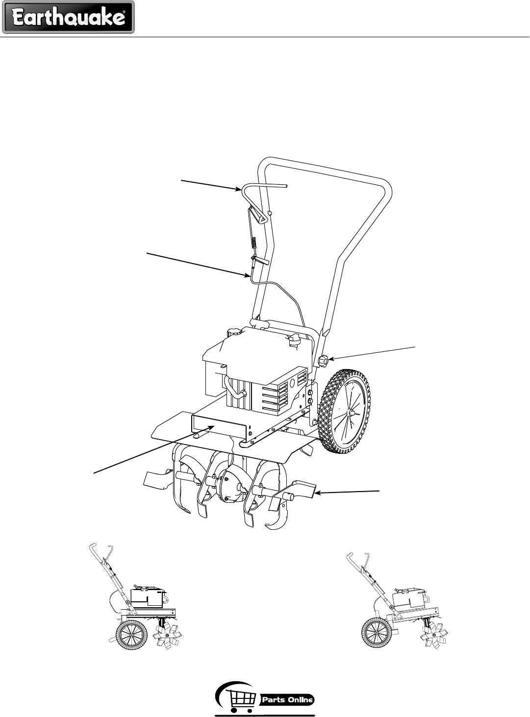
In the realm of gardening and landscaping, the effectiveness of your machinery is paramount. Understanding the various components that make up your cultivation device is crucial for optimal performance. Each element plays a significant role in ensuring that your equipment operates smoothly, allowing you to tackle any gardening task with ease and efficiency.
Having a clear representation of the machinery’s configuration can be immensely beneficial. It enables users to identify specific sections quickly, facilitating maintenance and repairs. By familiarizing yourself with the layout, you can ensure that every aspect of the equipment is functioning correctly, prolonging its lifespan and enhancing its overall efficiency.
Whether you’re a seasoned professional or a novice gardener, having access to detailed illustrations can aid in troubleshooting and understanding the intricacies of your machine. This knowledge empowers you to make informed decisions regarding repairs and upgrades, ensuring that your gardening endeavors are successful and productive.
Huskee Rear Tine Tiller Parts Diagram Article
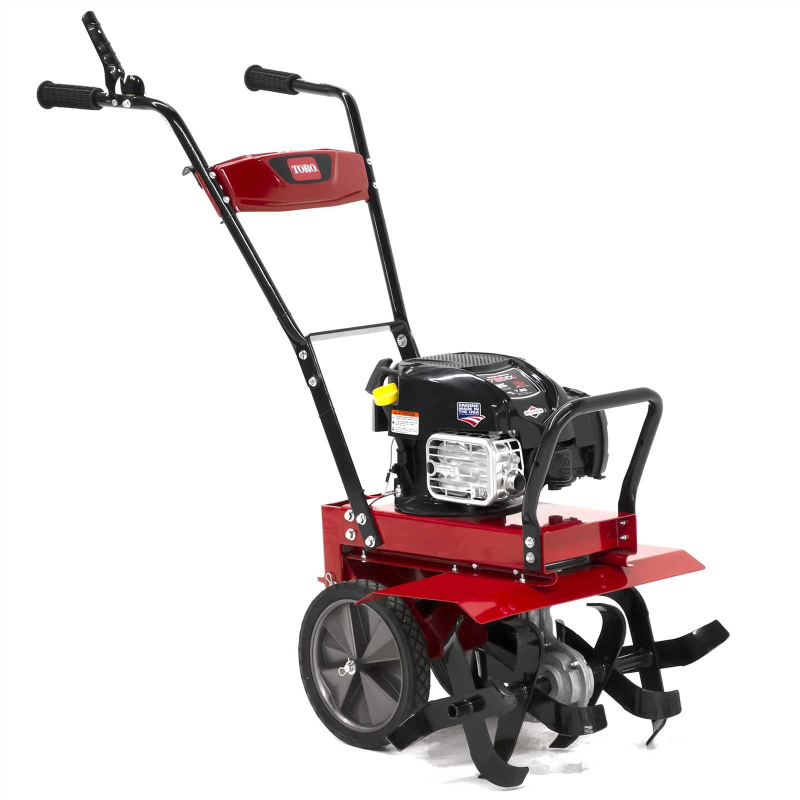
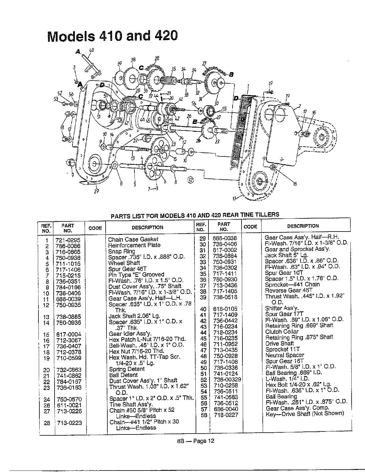
This section provides a comprehensive overview of the various components involved in a specific garden cultivation device. Understanding the intricate assembly of these elements is essential for effective maintenance and repair, ensuring optimal functionality and longevity of the equipment. The following information will help users identify and locate the different parts that contribute to the overall performance of the machine.
| Component Name | Description |
|---|---|
| Engine | The power source that drives the entire mechanism. |
| Transmission | Responsible for transferring power from the engine to the working parts. |
| Tine Assembly | Includes the blades that break up and aerate the soil. |
| Handle | The part used by the operator to guide and control the machine. |
| Wheels | Provide mobility and stability during operation. |
| Chassis | The main frame that supports all components and ensures durability. |
| Fuel Tank | Holds the fuel needed for the engine to operate. |
| Air Filter | Protects the engine by filtering out dust and debris from the air intake. |
Understanding the Engine Components
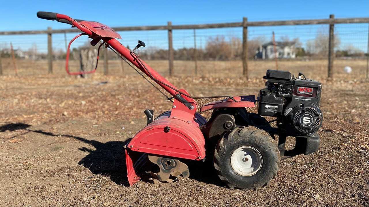
The power source is a crucial aspect of any outdoor machinery, playing a vital role in its overall functionality and performance. By grasping the key elements that make up this system, users can enhance their understanding of how their equipment operates and how to maintain it effectively.
At the heart of this mechanism is the combustion chamber, where fuel and air mix to create the energy needed for movement. This chamber is complemented by various components such as pistons, which transform the explosion’s force into linear motion, and crankshafts, which convert this motion into rotational power.
The fuel system also plays a significant role, ensuring the engine receives the proper mixture for optimal performance. It includes the fuel tank, where the energy source is stored, and the carburetor, which regulates the flow of fuel and air. A well-functioning fuel system is essential for smooth operation and efficiency.
Another critical aspect is the ignition system, which is responsible for initiating the combustion process. This system comprises spark plugs, which create the necessary spark to ignite the fuel-air mixture, ensuring that the engine runs reliably. Regular maintenance of these components is essential for maintaining performance.
Lastly, the cooling system is essential in preventing overheating, which can lead to significant damage. This system typically includes a radiator or fan to dissipate heat, maintaining optimal operating temperatures for the engine to function efficiently.
Exploring Gearbox and Transmission Parts
The efficiency of any machinery heavily relies on the intricate mechanisms within its drive system. Understanding the components responsible for power transfer can significantly enhance maintenance and repair efforts. This section delves into the critical elements that ensure optimal operation and longevity of the equipment.
Key Components of the Drive System
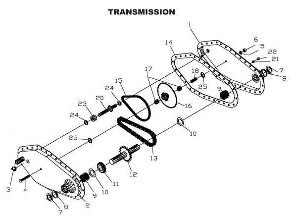
- Gearbox: This unit is essential for adjusting speed and torque, allowing the machine to perform various tasks effectively.
- Drive Shafts: These are responsible for transmitting rotational motion from the engine to the gearbox, enabling movement.
- Clutch Mechanism: This component engages and disengages power flow, providing control over the equipment’s operation.
- Bearings: These reduce friction between moving parts, ensuring smooth operation and prolonging the life of the machinery.
Common Issues and Maintenance Tips
- Regular Inspection: Periodically check the gearbox for signs of wear or damage.
- Lubrication: Ensure all moving components are adequately lubricated to minimize friction and prevent overheating.
- Alignment Checks: Verify that all shafts are properly aligned to prevent unnecessary strain on the transmission system.
- Replacement of Worn Parts: Timely replacement of degraded components is crucial for maintaining functionality.
Understanding these elements can aid in achieving better performance and reliability from the equipment. Regular attention to the drive system not only ensures smooth operation but also enhances the overall lifespan of the machine.
Identifying Clutch Mechanism Details
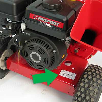
Understanding the intricacies of the engagement system is essential for effective operation and maintenance of garden equipment. This component plays a pivotal role in controlling the power transfer from the engine to the working parts, ensuring optimal performance and functionality.
To properly assess the engagement system, it is important to recognize its key elements and their functions. Here are the primary components to consider:
- Clutch Plate: This component engages and disengages the drive mechanism, allowing for controlled operation.
- Springs: These provide the necessary tension to maintain the clutch’s operational integrity, ensuring reliable performance.
- Lever Assembly: This part is responsible for manual engagement and disengagement of the clutch, allowing the user to control the equipment easily.
- Bell Housing: This protective casing surrounds the clutch mechanism, safeguarding it from debris and damage.
- Friction Discs: These are crucial for creating the necessary grip during operation, facilitating smooth engagement.
Each of these components plays a significant role in the overall functionality of the engagement system. Regular inspection and maintenance are recommended to ensure these elements remain in good condition, enhancing the longevity and effectiveness of your garden machinery.
Analyzing Tine and Tiller Blade Assembly
The functionality of cultivation equipment greatly depends on the interaction between its primary components. The assembly that includes the rotating elements plays a crucial role in soil preparation, ensuring effective mixing and aeration. Understanding the dynamics of these elements is essential for optimal performance and maintenance.
Understanding Component Interactions
In this context, the rotating blades engage with the ground, facilitating the breaking up of compacted soil. The effectiveness of this operation relies on the design and arrangement of the cutting edges. Properly aligned and maintained elements not only enhance efficiency but also extend the lifespan of the equipment. Any irregularities in these components can lead to subpar results and increased wear.
Maintenance and Adjustment Considerations
Regular inspection and adjustment of the assembly are critical for sustaining peak performance. Ensuring that the edges are sharp and free from damage allows for smoother operation. Additionally, periodic lubrication of moving parts minimizes friction and reduces the likelihood of mechanical failure. By prioritizing these aspects, users can achieve consistent results in their cultivation tasks.
Examining Handlebar and Control Panel Layout
In this section, we explore the arrangement and configuration of the handlebar and control panel components. It focuses on understanding the ergonomic design and functionality integration, highlighting how these elements contribute to the operational ease and user experience. The handlebar serves as the central point for maneuvering and control, while the control panel hosts various essential features and settings. By examining their layout, users can gain insight into the intuitive placement of controls and indicators, facilitating efficient operation and maintenance.
- Discussing the ergonomic design and functionality integration
- Highlighting the operational ease and user experience
- Exploring the arrangement and configuration of handlebar and control panel components
- Examining the intuitive placement of controls and indicators
- Understanding the central role of the handlebar in maneuvering and control
Inspecting Fuel System and Tank Components
Proper examination of the fuel delivery mechanism and storage container is essential for ensuring optimal performance and longevity of your equipment. Regularly assessing these components can prevent potential malfunctions and enhance efficiency during operation. A well-maintained fuel system contributes significantly to the reliability and effectiveness of your machinery.
Key Components to Examine
When inspecting the fuel system, it is crucial to focus on various elements that play a vital role in fuel management. Pay attention to the following components:
| Component | Function | Inspection Tips |
|---|---|---|
| Fuel Tank | Stores fuel for the engine. | Check for leaks, corrosion, and proper sealing. |
| Fuel Lines | Transports fuel from the tank to the engine. | Look for cracks, blockages, or loose connections. |
| Fuel Filter | Removes impurities from the fuel. | Inspect for clogs and replace if necessary. |
| Fuel Pump | Delivers fuel to the engine. | Listen for unusual noises and check for proper operation. |
Maintaining Fuel System Integrity
Ensuring the integrity of the fuel system requires regular maintenance. Clean or replace filters as needed, and keep the tank filled to prevent moisture accumulation. Furthermore, using high-quality fuel can help maintain system efficiency and prolong the life of your components. Proper storage and handling practices will also contribute to the overall health of the fuel delivery system.
Detailing Belt and Pulley System Structure
The belt and pulley assembly plays a crucial role in the operation of various machinery, facilitating the transfer of power between components. This intricate system is designed to optimize efficiency, ensuring that motion is transmitted smoothly and effectively. Understanding its structure and functionality can significantly enhance maintenance and troubleshooting efforts.
At the core of this system are the belts, which are flexible loops that transmit mechanical power by connecting different shafts. The pulleys serve as the guiding mechanism, providing the necessary support and direction for the belts. Together, they work in unison to convert rotational motion from one source to another, allowing the entire apparatus to function seamlessly.
| Component | Description |
|---|---|
| Belt | A flexible loop that transfers power by connecting pulleys. |
| Pulley | A wheel on an axle or shaft designed to support movement and change direction of the belt. |
| Tensioner | A component that maintains the appropriate tension on the belt to prevent slippage. |
| Idler Pulley | A pulley used to guide or provide tension to the belt without driving any load. |
| Drive Pulley | The primary pulley connected to the power source, responsible for driving the belt. |
Proper maintenance of the belt and pulley arrangement is essential for optimal performance. Regular inspection for wear and tear, as well as ensuring correct tension, can prolong the lifespan of these components and prevent unexpected failures.
Overview of Safety Features and Maintenance Tips
Ensuring optimal performance and longevity of garden equipment requires understanding both safety mechanisms and routine care. This section highlights essential protective features designed to minimize risks during operation, alongside practical suggestions for maintenance that enhance functionality and durability.
One critical safety aspect is the presence of protective shields that prevent accidental contact with moving components. Operators should always verify that these shields are intact and securely fastened before use. Additionally, employing proper personal protective equipment, such as gloves and eye protection, significantly reduces the risk of injury during operation.
Regular inspections of the machinery are paramount. Check for any loose screws, worn belts, or damaged components that could compromise safety or performance. It is advisable to clean the equipment after each use, removing any debris that may accumulate, which can lead to mechanical failures or hazards.
Furthermore, ensure that all fluids are at the recommended levels, as this not only supports efficient operation but also prolongs the life of the engine. Adhering to the manufacturer’s maintenance schedule, including oil changes and filter replacements, is vital for optimal functioning.
In summary, prioritizing safety features and conducting regular maintenance checks are essential practices that contribute to safe and efficient operation. By staying vigilant and proactive, operators can ensure a reliable and effective experience with their gardening equipment.