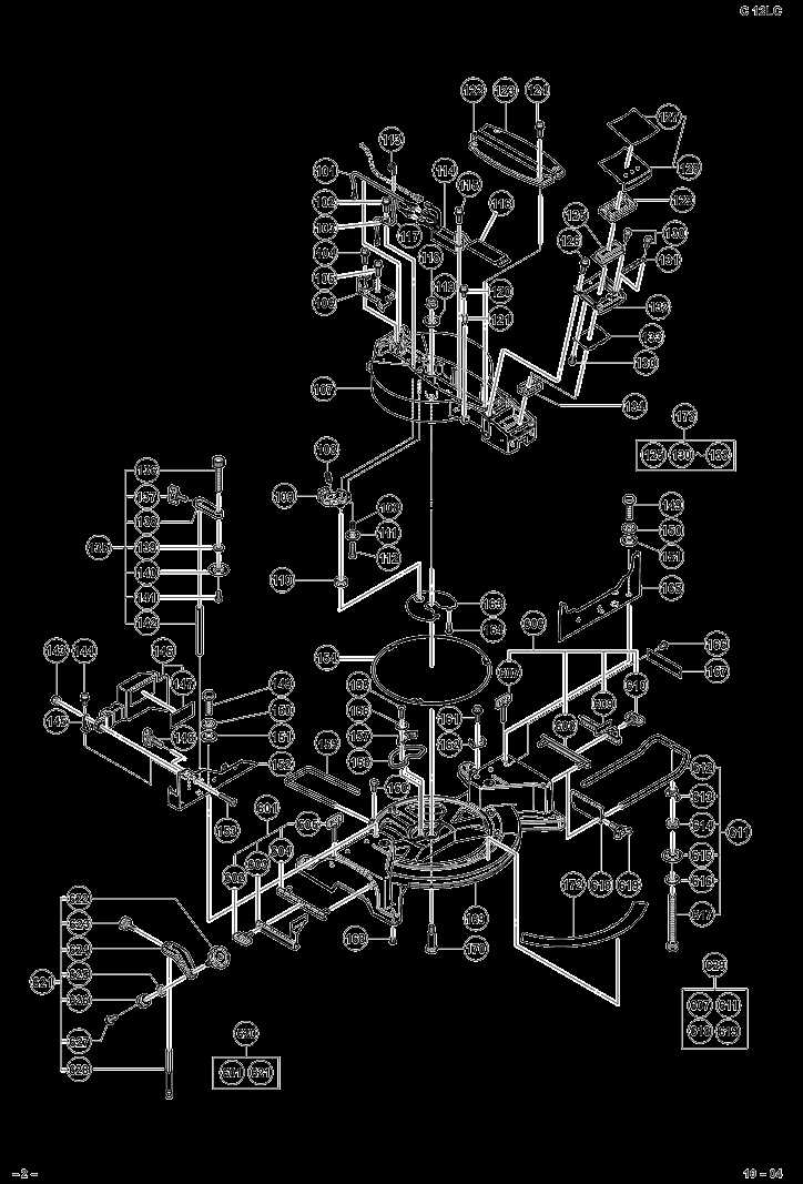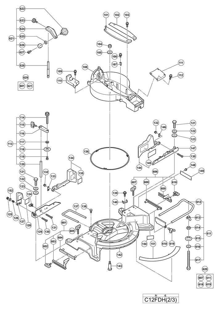
When it comes to high-performance machinery, having a comprehensive understanding of the internal structure is crucial for optimal functionality. This section explores the intricate arrangement of components that contribute to the effective operation of power tools.
By analyzing the schematic representation of these elements, users can gain insights into maintenance and repair processes. Such knowledge not only enhances the lifespan of the equipment but also ensures safety during its operation.
Whether you are a seasoned professional or a hobbyist, familiarizing yourself with these configurations is the ultimate step towards achieving efficiency and precision in your projects. Join us as we delve into the specifics that make these tools reliable and effective.
Understanding Hitachi C12FDH Components
Grasping the intricacies of power tools involves a keen awareness of their individual elements. Each component plays a vital role in ensuring optimal performance, safety, and durability. A comprehensive understanding of these elements not only aids in maintenance but also enhances the overall user experience.
Key Elements and Their Functions

Among the most critical components are the motor, which powers the tool, and the blade, responsible for cutting precision. The casing provides structural integrity, while the base ensures stability during operation. Additionally, the handles are designed for comfort, allowing for prolonged use without strain.
Maintenance and Repair Considerations
Regular inspection of each part can prevent unnecessary wear and tear. Identifying signs of damage early–such as cracks in the housing or dull blades–can save time and money in repairs. Understanding how each element interacts promotes better care and prolongs the lifespan of the equipment.
Overview of Hitachi C12FDH Parts
This section provides a comprehensive look at the various components of a specific cutting tool, emphasizing their functions and interconnections. Understanding each element is essential for effective maintenance and optimal performance. A well-organized assembly of parts not only enhances durability but also contributes to the efficiency of the equipment.
Key features include the motor, which powers the tool, and the blade, responsible for making precise cuts. Additionally, the housing protects internal mechanisms while offering user-friendly controls. Other essential components such as the base, support arms, and safety features play vital roles in ensuring stability and safety during operation.
Maintaining familiarity with these components enables users to troubleshoot issues more effectively and perform necessary repairs. This knowledge ultimately leads to a more productive experience and prolongs the lifespan of the equipment.
Importance of Accurate Parts Diagrams
Having precise visual representations of components is crucial in any mechanical or electronic system. These illustrations serve as invaluable tools for maintenance, repair, and assembly tasks, enabling users to understand how each element fits into the whole.
- Facilitates quick identification of components.
- Enhances efficiency in repairs and replacements.
- Reduces the risk of errors during assembly.
- Improves communication among technicians and engineers.
Inaccuracies can lead to costly mistakes and prolong downtime, making it essential to rely on detailed and trustworthy visual guides for optimal performance.
How to Read the Parts Diagram
Understanding an assembly illustration is crucial for effective maintenance and repair. It provides a visual representation of the components involved, enabling users to identify and locate each item efficiently. Familiarity with these illustrations ensures that users can execute tasks accurately and with confidence.
Key Elements to Identify
Begin by examining the overall layout. Each section is typically organized by groups of related components. Look for labels and numbers that correspond to the parts list, which usually accompanies the visual guide. This information helps in pinpointing specific items for replacement or repair.
Interpreting Symbols and Annotations
Pay attention to any symbols or annotations that may appear alongside the visuals. These often indicate the type of connection, assembly instructions, or special considerations. Understanding these details allows for a smoother and more efficient assembly process, ultimately enhancing the overall experience.
Common Replacement Parts for C12FDH
When maintaining your cutting tool, it’s essential to be aware of the most frequently replaced components. Understanding these vital elements ensures optimal performance and longevity of the equipment. Here, we explore some common elements that may require replacement over time due to wear and tear or damage.
Blade Assembly
The blade assembly is crucial for efficient cutting. Over time, blades can dull or sustain chips, necessitating replacement. Choosing high-quality replacements will significantly impact the accuracy and ease of your cutting tasks.
Motor Brushes
Motor brushes play a pivotal role in the functionality of the tool. As these components wear down, the performance can decline, leading to reduced power and efficiency. Regular inspection and timely replacement of these brushes can prevent unexpected failures and maintain smooth operation.
Remember: Regular maintenance and timely replacements not only enhance performance but also extend the lifespan of your equipment.
Troubleshooting with Parts Diagrams
Identifying and resolving issues in machinery can often feel daunting, but visual aids can simplify the process significantly. These illustrations provide a clear representation of components, helping users pinpoint problems efficiently. By understanding the layout and function of each element, one can systematically address malfunctions and perform necessary repairs.
When faced with a malfunction, having a detailed visual reference allows for quick identification of affected parts. This knowledge facilitates targeted troubleshooting, enabling users to focus their efforts on specific areas rather than attempting a trial-and-error approach. Moreover, recognizing how components interact can reveal underlying issues that may not be immediately apparent.
Utilizing these resources not only streamlines the repair process but also enhances maintenance practices. Regularly consulting these visuals during inspections can help in catching potential problems early, ultimately prolonging the lifespan of the equipment. By making informed decisions based on accurate representations, users can ensure their machines operate smoothly and efficiently.
Where to Find Official Diagrams

Finding authentic schematics for equipment maintenance can greatly enhance the efficiency and effectiveness of repairs. These detailed illustrations provide crucial insights into the assembly and components of the machinery, ensuring that users have access to reliable information.
One of the best resources for locating official schematics is the manufacturer’s website. Most companies offer downloadable manuals and schematics in the support or resources section. Additionally, authorized dealers may provide printed or digital copies, ensuring the user has access to the most accurate and up-to-date information.
Online forums dedicated to machinery enthusiasts and professionals can also be valuable. Members often share links to official resources or even upload diagrams they have acquired, fostering a community of shared knowledge. Furthermore, specialized publications and repair guides sometimes include official schematics or references to where they can be obtained.
Maintenance Tips for C12FDH Components
Proper upkeep of your equipment is essential for longevity and optimal performance. Regular maintenance can prevent costly repairs and ensure safety during operation. Here are some practical suggestions to help you keep the critical elements of your machine in top condition.
| Component | Maintenance Tips |
|---|---|
| Motor | Inspect regularly for any signs of wear. Keep the motor clean and free from dust. Lubricate moving parts as specified in the manual. |
| Blade | Ensure that blades are sharp for efficient cutting. Regularly check for any nicks or damage, and replace them when necessary. |
| Base | Keep the base free from debris to ensure stability. Inspect it for any cracks or signs of wear that could affect performance. |
| Switch | Test the functionality of the switch periodically. Clean any accumulated dirt to ensure reliable operation. |
| Cooling System | Check the cooling vents for blockages. Clean them to maintain proper airflow and prevent overheating. |
Following these guidelines will help enhance the efficiency and reliability of your equipment. Always refer to the manufacturer’s recommendations for specific maintenance practices to ensure the best care for your machine.
Impact of Genuine Parts on Performance
Utilizing authentic components significantly influences the efficiency and longevity of equipment. When manufacturers produce their machines, they meticulously design each element to work seamlessly together. Authentic replacements ensure this harmony, leading to optimal functionality and reduced risks of malfunction.
Counterfeit or generic substitutes may appear cost-effective initially, but they often compromise overall performance. These alternatives can result in increased wear and tear, leading to premature failures and costly repairs. Hence, investing in original replacements can ultimately save time and money.
| Factor | Genuine Components | Generic Components |
|---|---|---|
| Durability | High | Medium |
| Performance | Optimal | Variable |
| Warranty | Included | Often Not Available |
| Long-term Cost | Lower | Higher |
In conclusion, opting for authentic replacements not only enhances immediate performance but also ensures reliability over time, making it the ultimate choice for anyone seeking sustained excellence in their machinery.