Maintaining and repairing outdoor machinery requires a clear understanding of how its various components work together. Knowing the layout and connections of key elements can greatly simplify upkeep and troubleshooting, ensuring that the equipment performs efficiently and lasts longer. In this guide, we will explore the essential aspects of assembly and arrangement without delving into unnecessary technical jargon.
When dealing with mechanical devices, it’s crucial to recognize how each element plays a role in the overall function. A clear overview of the system can help users identify potential issues and perform necessary adjustments. This not only saves time but also prevents unnecessary wear and tear on the machine, promoting its longevity.
In the following sections, you will find a detailed breakdown of individual components, their placements, and how they interact within the broader framework. This knowledge is vital for anyone seeking to maintain their tools in top condition, ensuring smooth operation and effective results in the long run.
Comprehensive Overview of Bolens BL110 Components
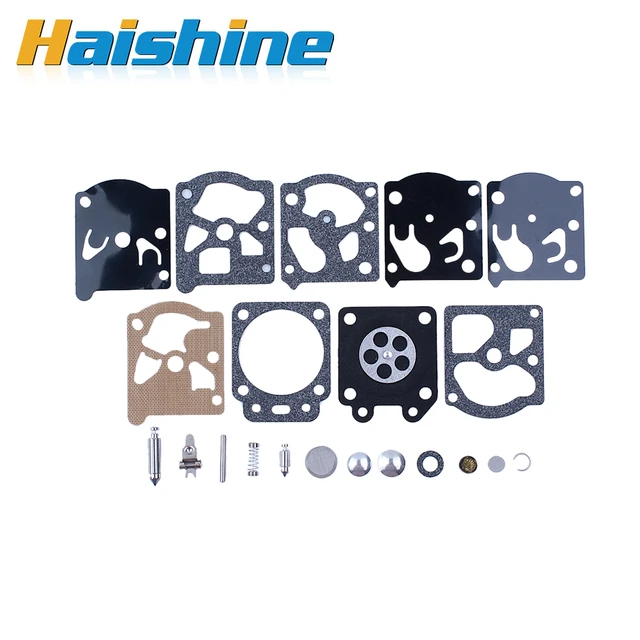
This section provides an in-depth examination of the various elements that contribute to the overall functionality of a specific outdoor equipment model. Understanding the individual components is essential for effective maintenance, repair, and enhancement of performance.
Key components include:
- Engine: The heart of the machine, responsible for power generation and performance.
- Chassis: The frame that supports all other elements, ensuring stability and durability.
- Cutting Mechanism: This includes blades and attachments that perform the cutting action necessary for lawn care.
- Fuel System: Comprising the tank, lines, and filters that supply the engine with fuel.
- Electrical System: Encompasses the ignition components and wiring essential for starting and operating the machine.
Each of these components plays a vital role in the equipment’s operation and longevity. Regular inspection and timely replacement of worn parts can significantly improve performance and efficiency.
For a successful upkeep, users should familiarize themselves with:
- The function of each part and its interaction with other elements.
- The recommended maintenance schedules for different components.
- Common issues that may arise and their respective solutions.
Ultimately, a thorough understanding of these elements enhances user experience and ensures optimal operation of the equipment.
Key Features of the Bolens BL110 Engine
The engine of this model stands out due to its robust construction and efficient performance. Designed to meet various operational demands, it integrates advanced technologies to enhance functionality and reliability. This section will explore the distinctive characteristics that contribute to its effectiveness and user satisfaction.
Power and Performance
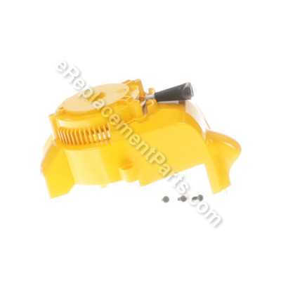
The powertrain delivers impressive torque, enabling the machine to tackle tough tasks with ease. Its reliable ignition system ensures quick starts, even in challenging conditions. Additionally, the fuel efficiency is optimized to provide extended operation time without frequent refueling, making it ideal for long projects.
Durability and Maintenance
Crafted with high-quality materials, this engine offers exceptional durability, capable of withstanding rigorous use. Regular maintenance is simplified through accessible components, allowing users to perform upkeep with minimal effort. The design promotes longevity, ensuring that the engine remains a dependable choice for various applications.
Understanding the Fuel System Layout
The configuration of the fuel system is crucial for the efficient operation of any engine. A well-designed fuel arrangement ensures that the combustion process occurs optimally, contributing to better performance and longevity of the machine. By examining the various components and their functions, one can gain insights into how the system supports the overall functionality of the equipment.
Key elements of the fuel system typically include:
- Fuel Tank: The reservoir that stores the fuel, providing a reliable supply to the engine.
- Fuel Pump: This component is responsible for transporting fuel from the tank to the engine, maintaining appropriate pressure for optimal performance.
- Fuel Filter: A crucial part that cleanses the fuel of impurities, preventing contaminants from entering the engine and causing damage.
- Fuel Lines: The pathways through which fuel flows, connecting the tank, pump, and engine. Proper routing is essential to prevent leaks.
- Carburetor or Fuel Injector: The component that mixes air and fuel in the right ratio for efficient combustion.
Understanding each component’s role helps in diagnosing issues and performing maintenance effectively. Regular checks and servicing of the fuel system can prevent common problems and ensure smooth operation.
In summary, the fuel system layout plays a pivotal role in the performance and reliability of an engine. Familiarity with its components allows operators to maintain their equipment better and address potential issues proactively.
Air Filter Assembly and Maintenance Tips
Ensuring optimal performance of your outdoor equipment requires proper attention to the air filtration system. This component plays a crucial role in preventing contaminants from entering the engine, thereby enhancing its efficiency and longevity.
Assembly Instructions: To assemble the air filtration system, start by locating the air filter housing. Carefully position the filter inside the housing, ensuring it fits snugly. Secure the housing lid to protect the filter from debris and ensure an airtight seal. Regularly check for any signs of wear and tear on the housing to maintain its effectiveness.
Maintenance Recommendations: Routine maintenance of the air filter is vital. Clean or replace the filter as needed, ideally every 25 hours of operation or more frequently in dusty conditions. To clean, remove the filter, gently tap it to dislodge dirt, and use compressed air to blow out any remaining particles. Always inspect for damage before reinstallation.
Importance of Regular Checks: Regularly checking the air filtration system not only enhances the machine’s performance but also reduces fuel consumption and minimizes emissions. A well-maintained air filter allows the engine to breathe freely, ensuring smooth operation.
Exploring the Ignition System Parts
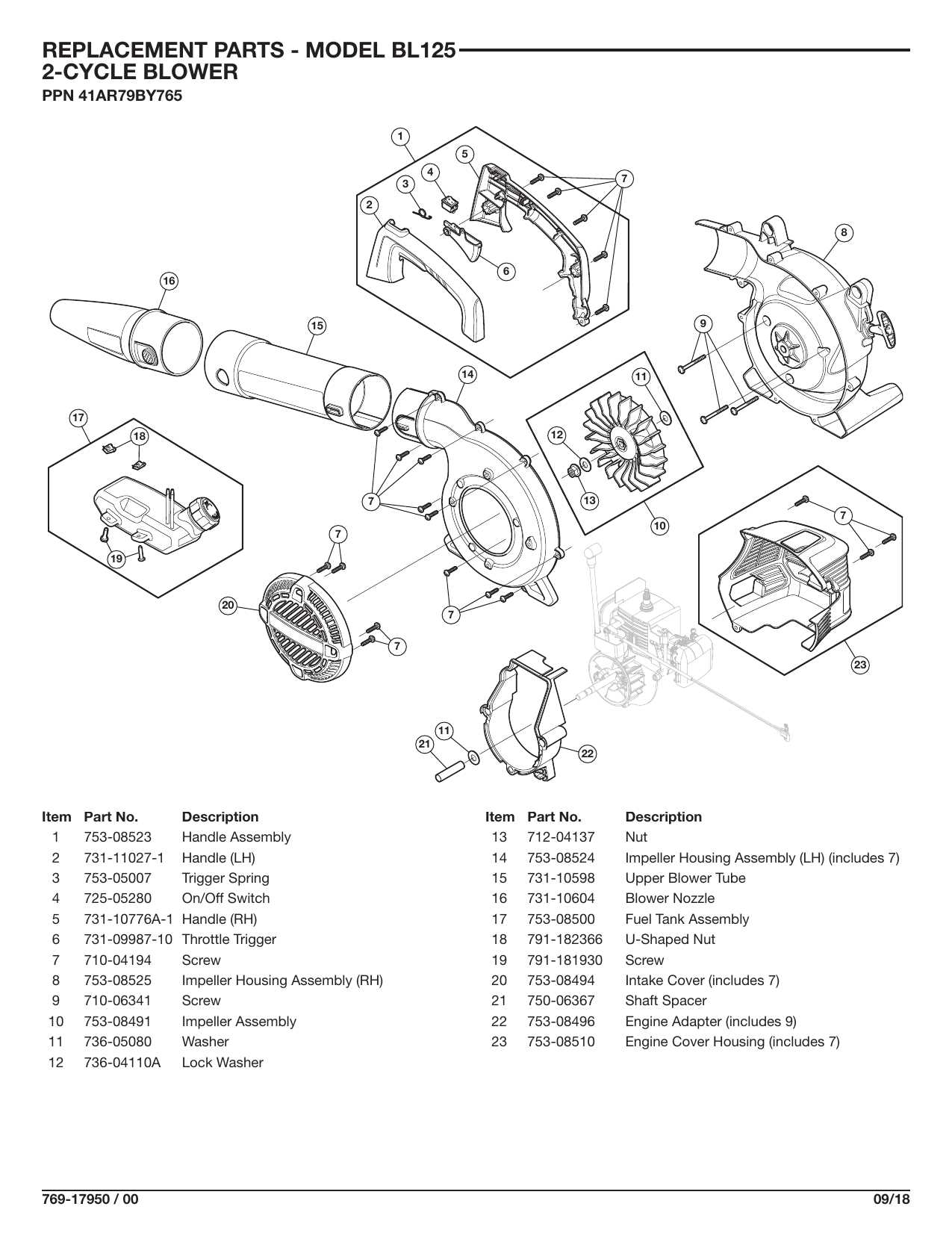
The ignition system is a crucial component that ensures a machine starts reliably and runs smoothly. Understanding its various elements can greatly aid in troubleshooting and maintenance. Each part plays a specific role in the ignition process, contributing to the overall functionality of the engine.
Key Components of the Ignition System
- Spark Plug: This part ignites the air-fuel mixture, creating the necessary combustion to power the engine.
- Ignition Coil: Responsible for transforming battery voltage into a higher voltage, which is needed to create a spark at the spark plug.
- Distributor: Distributes the high voltage from the ignition coil to the correct cylinder at the right time.
- Ignition Module: Controls the timing of the spark and ensures efficient engine performance.
Importance of Maintenance
Regular maintenance of the ignition system components is essential for optimal engine performance. Neglecting these parts can lead to poor starting, misfires, and reduced efficiency. Keeping a close eye on wear and tear can save time and resources in the long run.
- Inspect spark plugs regularly for signs of wear.
- Check ignition coils for any damage or corrosion.
- Ensure proper connections in the distributor and ignition module.
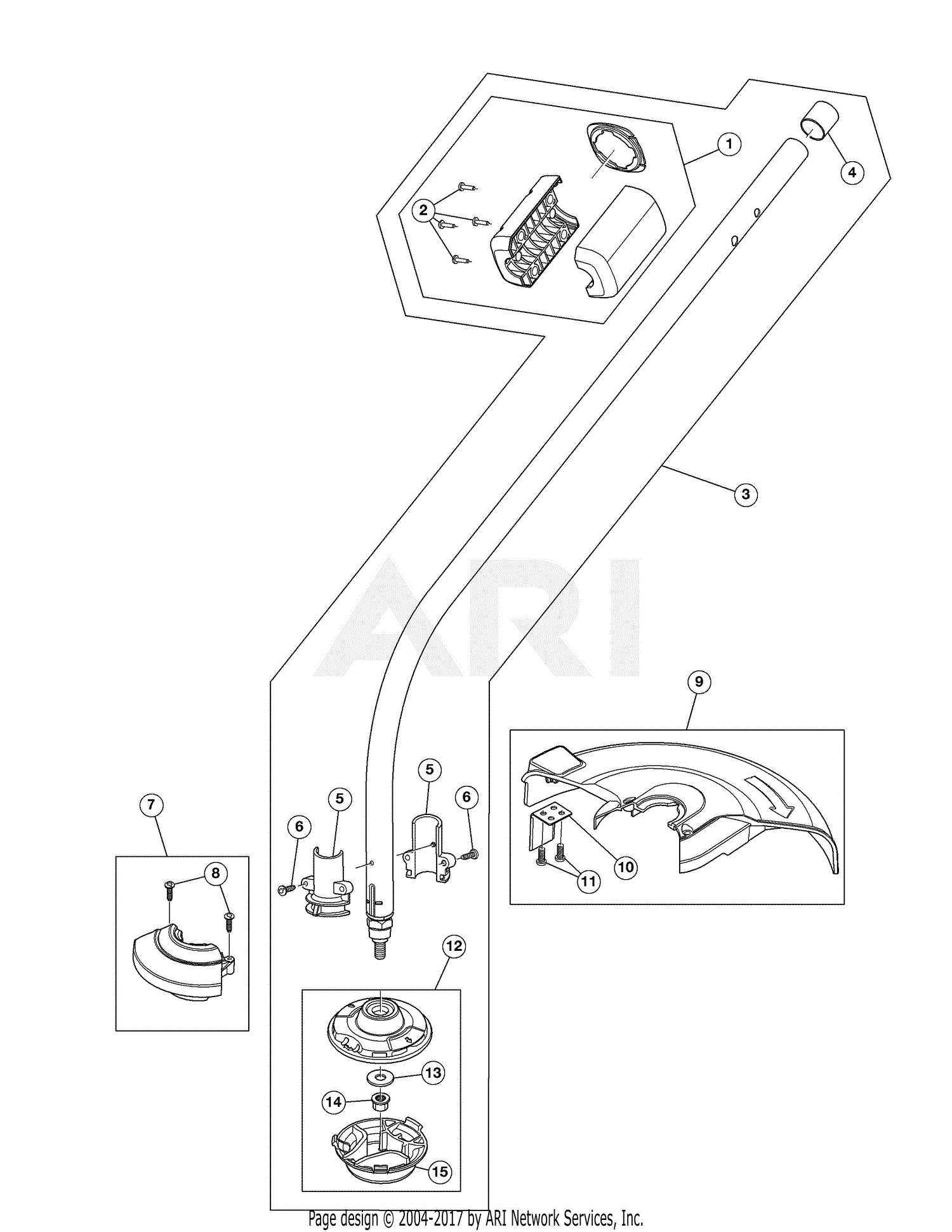
Trimmer Head: Parts and Functionality
The trimmer head is a crucial component of any cutting tool designed for maintaining greenery. It plays a significant role in the overall performance, influencing how effectively the device can tackle various types of vegetation. Understanding its structure and operation can enhance both usage and maintenance practices.
Key components of the trimmer head include:
- Housing: This outer shell protects the internal mechanisms and holds everything in place.
- Spool: The spool is where the cutting line is wound. Its design affects how much line can be stored and how easily it can be dispensed.
- Cutting Line: The flexible material that performs the actual cutting. Different types of lines can be used depending on the job at hand.
- Retention Cap: This secures the spool and cutting line within the housing, preventing them from falling out during operation.
- Trimmer Head Assembly: The entire unit that includes all components, facilitating easy attachment to the main body of the cutting tool.
The functionality of the trimmer head is determined by its design and the materials used. Key aspects include:
- Line Dispensing: Effective line dispensing mechanisms allow for continuous operation without frequent interruptions to reload.
- Durability: High-quality materials enhance the longevity of the trimmer head, ensuring it can withstand wear and tear.
- Versatility: Some models allow for different types of cutting lines, enabling users to adapt to various tasks.
Proper maintenance of the trimmer head ensures optimal performance, making it essential for achieving desired results in lawn care and landscaping tasks.
Handle and Control Mechanism Breakdown
The handle and control mechanism is a crucial component of any outdoor equipment, facilitating user interaction and overall functionality. This section delves into the various elements that comprise this system, highlighting their roles and importance in ensuring efficient operation.
Handle Assembly: The handle assembly serves as the primary interface between the operator and the machine. Its design must prioritize ergonomics to minimize fatigue during extended use. Different configurations may offer varying levels of comfort and control.
Control Levers: Control levers are essential for regulating the machine’s functions, such as speed and direction. Their placement and responsiveness can significantly impact the user experience, making intuitive design paramount. Over time, wear and tear may necessitate replacement or adjustment to maintain optimal performance.
Cabling System: The cabling system links the control levers to the operational components. Proper maintenance of these cables is vital, as fraying or kinking can lead to malfunction. Regular inspections can help prevent potential issues and ensure smooth operation.
Safety Features: Integrated safety features within the handle and control assembly enhance user protection. These mechanisms can include emergency shut-off switches and safety locks, providing an added layer of security during operation.
Understanding the intricacies of the handle and control mechanism is essential for effective maintenance and troubleshooting. Regular assessment of each component can lead to improved performance and longevity of the equipment.
Detailed View of the Drive Shaft Components
The drive shaft is a crucial element in the mechanical transmission system, facilitating power transfer from the engine to the wheels. Understanding its individual components is essential for effective maintenance and troubleshooting. Each part plays a specific role in ensuring smooth operation and reliability.
| Component | Description | Function |
|---|---|---|
| U-Joint | A flexible coupling that allows for rotational movement. | Transmits torque while accommodating angular changes. |
| Drive Shaft Tube | The main shaft that connects the engine and the wheels. | Houses other components and transmits rotational force. |
| End Yoke | Attachment point for connecting to the differential or gearbox. | Provides a secure connection for effective power transfer. |
| Slip Joint | A mechanism that allows for length adjustment. | Accommodates movement caused by suspension travel. |
| Bearing | Support structures that minimize friction during rotation. | Ensures smooth operation and reduces wear on components. |
Each of these components is vital to the overall performance and durability of the system. Regular inspection and maintenance can prevent potential failures and enhance longevity.
Replacing and Maintaining the Cutting Line
Ensuring optimal performance of your outdoor equipment involves regular attention to the cutting mechanism. This component plays a crucial role in achieving clean and efficient trimming. Understanding how to properly replace and maintain this line not only enhances your machine’s effectiveness but also extends its lifespan.
Replacement Process
Begin by disconnecting the power source to prevent any accidental activation. Carefully remove the spool from the device, following the manufacturer’s guidelines. It’s essential to select the appropriate line thickness for your specific model, as this will ensure compatibility and efficiency. When installing the new line, make sure to wind it evenly and securely around the spool, adhering to the designated winding direction.
Maintenance Tips
To maintain the cutting line in optimal condition, regularly check for signs of wear or damage. Keeping the line clean and free from debris is crucial; debris can lead to improper functioning and even damage the equipment. Additionally, store the device in a cool, dry place to prevent the line from becoming brittle or degrading over time. Periodically lubricating the spool can also help in reducing friction, ensuring smoother operation.
By following these guidelines, you can significantly improve the efficiency and durability of your cutting tool, allowing you to tackle outdoor tasks with ease and precision.