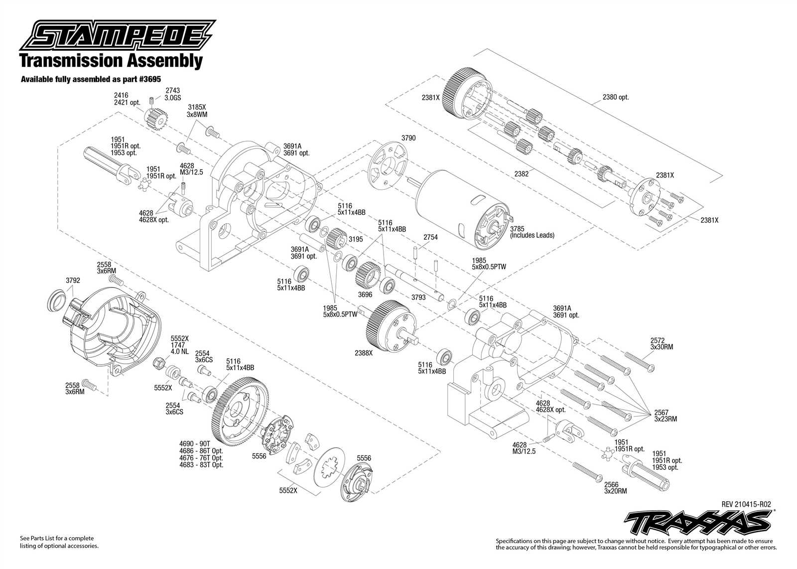
In the realm of technical illustrations, a powerful method exists to provide clarity and insight into complex structures. This approach breaks down components to reveal their relationships and functions, making it easier to grasp intricate designs. By showcasing elements in a detailed manner, users can better comprehend assembly, maintenance, and repairs.
Such representations serve not only as educational tools but also as essential resources in various industries, from manufacturing to engineering. They allow individuals to visualize how each component fits together, thereby enhancing understanding and facilitating effective communication among team members. With this clarity, tackling challenging projects becomes a more manageable endeavor.
Ultimately, engaging with these detailed visuals can lead to improved efficiency and effectiveness in both learning and application. By examining each segment thoroughly, one can delve into the nuances of construction, resulting in a comprehensive grasp of the subject matter.
Understanding Exploded Parts Diagrams
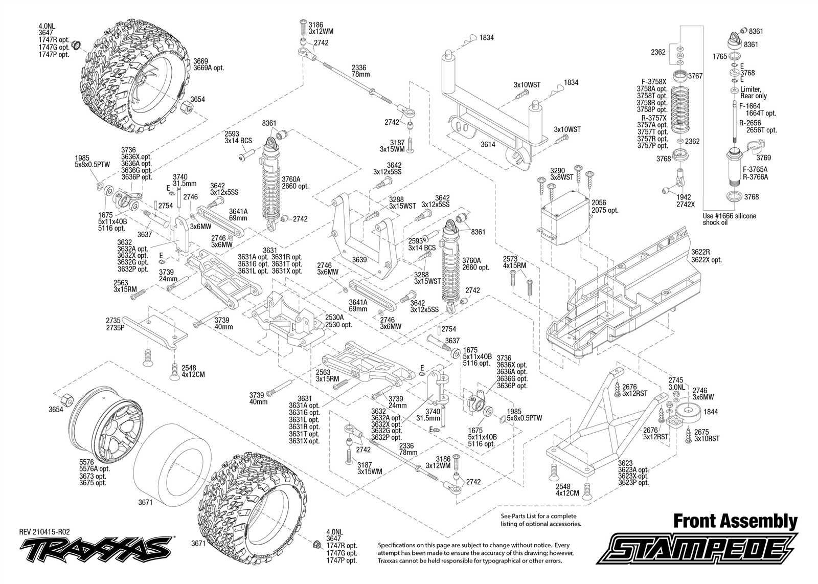
Visual representations that break down complex assemblies into their individual components play a crucial role in various fields. They provide a clear overview of how each element fits together, facilitating better comprehension and assembly processes.
These illustrations serve multiple purposes:
- Enhancing clarity in intricate designs
- Assisting in repair and maintenance tasks
- Improving instructional materials for users
When analyzing such visuals, consider the following aspects:
- Component Identification: Each element is labeled for easy recognition.
- Assembly Order: The layout often indicates the sequence for putting everything together.
- Relationship Visualization: Shows how parts interact and support one another.
Understanding these representations ultimately enhances efficiency and accuracy in both manufacturing and maintenance. They are invaluable tools for engineers, technicians, and hobbyists alike.
History of Exploded Views in Design
The visualization of complex structures has evolved significantly over time, serving as a crucial tool for understanding assembly and functionality. This approach allows designers and engineers to convey intricate details clearly, facilitating communication and collaboration across various fields.
Early Beginnings
In ancient times, artisans and builders utilized rudimentary sketches to represent their creations. As technology advanced, these illustrations became more sophisticated, reflecting an increasing need for clarity in mechanical design and architecture.
Modern Applications
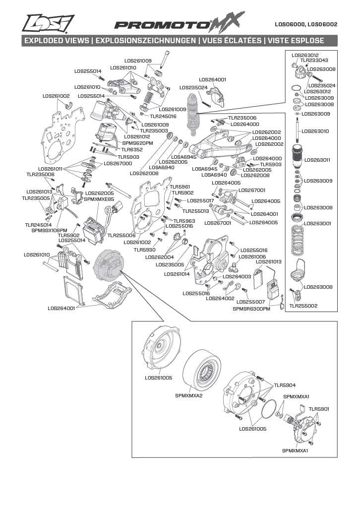
With the advent of computer-aided design (CAD) in the late 20th century, the technique gained new dimensions. Today, designers leverage advanced software to create detailed visualizations that enhance user comprehension and streamline the production process. This evolution showcases the ultimate blend of artistry and functionality in technical illustration.
Key Components of an Exploded Diagram
Understanding the essential elements of a disassembled representation is crucial for effective communication and analysis. These visual aids serve to clarify complex structures by highlighting individual elements and their relationships. Each component plays a vital role in ensuring that the viewer comprehends both the overall assembly and the significance of each section.
Structural Elements
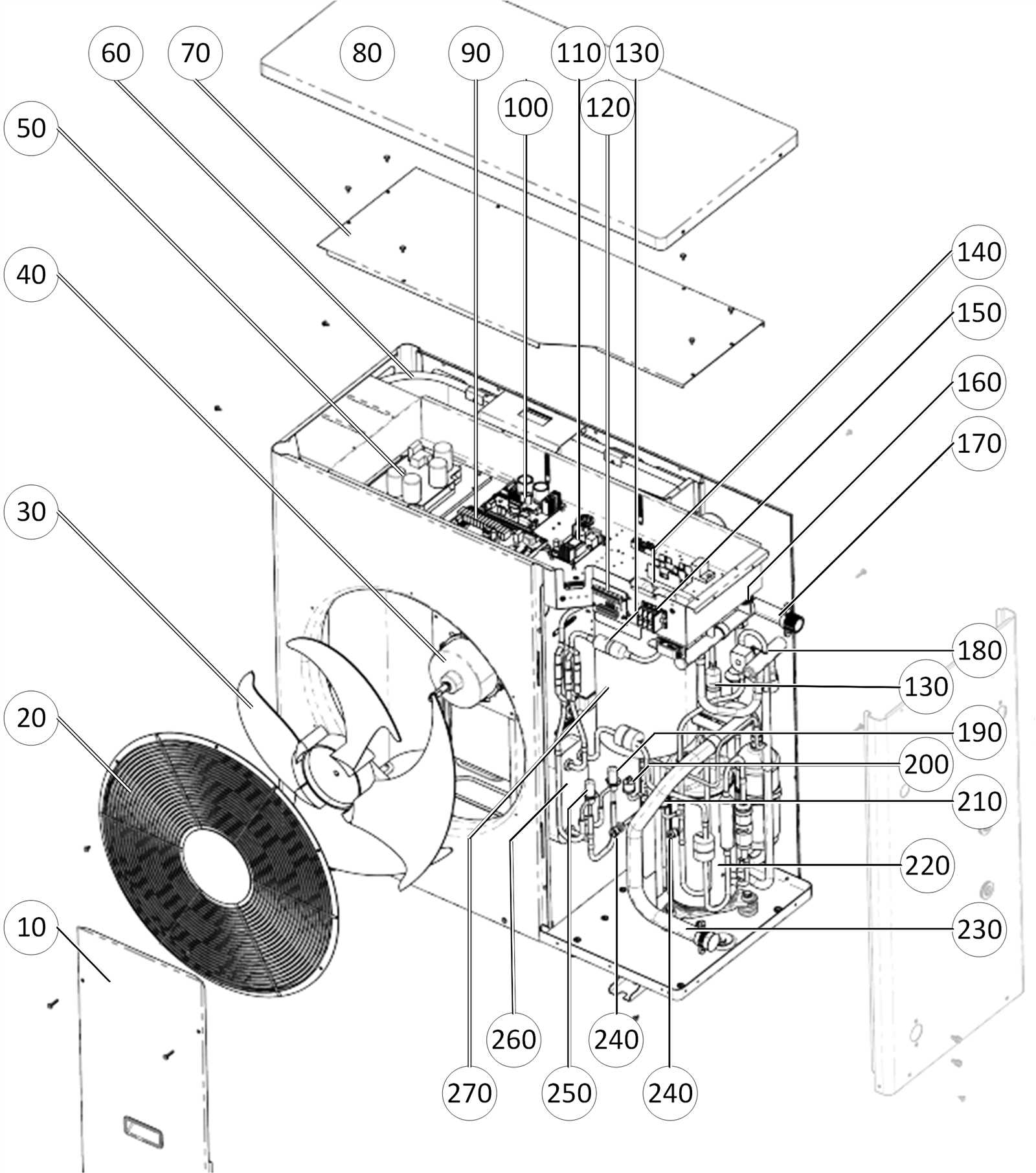
At the core of any disassembled visualization are the structural elements. These include the main body and supporting frameworks that define the overall configuration. Identifying these parts allows users to grasp how each section contributes to the functionality and stability of the entire assembly.
Annotations and Labels
Another critical aspect involves annotations and labels. These textual additions provide context, offering explanations and details that enhance understanding. Clear labeling ensures that viewers can quickly identify each section, while annotations can elaborate on specific functionalities or features, bridging the gap between visual representation and practical application.
Applications in Engineering and Manufacturing
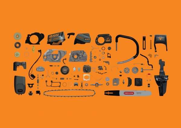
The visual representation of components and their relationships plays a crucial role in various industries. This approach enhances understanding, facilitates communication, and improves efficiency throughout the design and production processes.
- Design Development: Visual tools aid engineers in conceptualizing and refining their ideas.
- Assembly Instructions: Clear illustrations simplify complex assembly tasks, reducing errors.
- Maintenance and Repair: Detailed representations assist technicians in identifying and resolving issues effectively.
- Training and Education: Visual aids enhance learning experiences for new employees and students.
- Quality Control: Visual clarity helps ensure compliance with standards during manufacturing.
Ultimately, these techniques foster collaboration among teams, streamline workflows, and contribute to the overall success of engineering and manufacturing projects.
Benefits of Using Exploded Diagrams
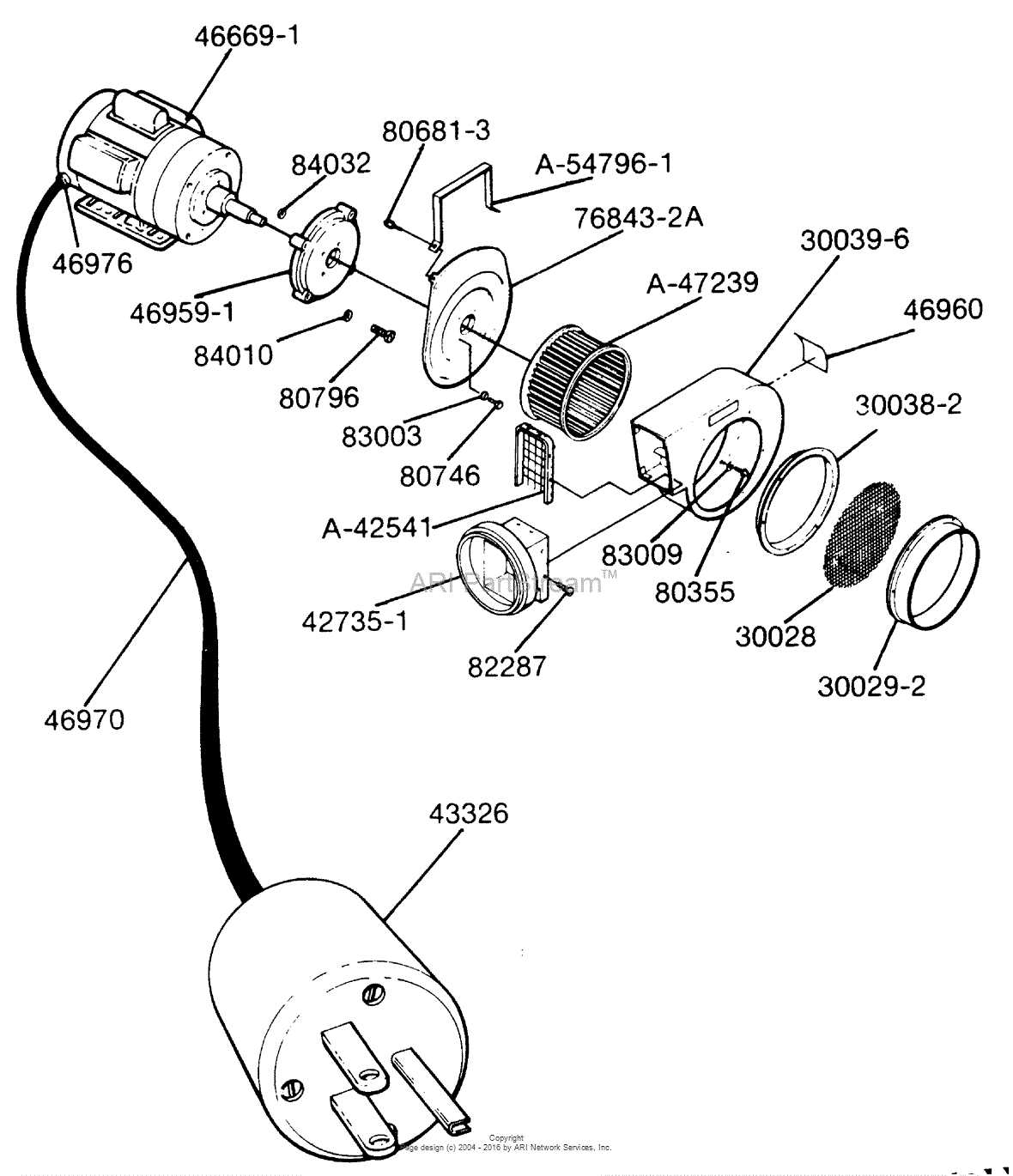
Visual representations that break down complex structures into their individual elements offer numerous advantages in various fields. They facilitate better understanding and communication by providing clarity and simplifying intricate designs. By allowing viewers to see components in relation to one another, these illustrations enhance learning and retention, making them invaluable tools in education, engineering, and design.
Enhanced Clarity and Understanding
One of the primary benefits of utilizing these visual aids is their ability to promote clarity. When a structure is displayed with its components separated, it becomes easier to identify how each piece functions and interacts within the whole. This approach not only aids comprehension but also assists in troubleshooting and maintenance.
Effective Communication Tool
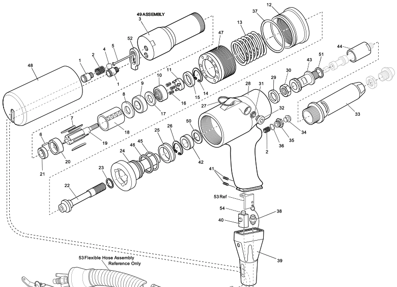
In collaborative environments, these visuals serve as powerful communication tools. They provide a common reference point for team members, ensuring that everyone is aligned on the design and functionality of a project. This reduces the likelihood of misunderstandings and errors during the development process.
| Advantages | Description |
|---|---|
| Improved Learning | Facilitates retention of information through visual engagement. |
| Efficient Problem Solving | Helps in identifying issues by isolating individual components. |
| Streamlined Collaboration | Acts as a reference point for discussions and feedback among team members. |
Techniques for Creating Exploded Views
Crafting a visual representation that disassembles a complex object into its individual components requires a blend of artistic insight and technical skill. This approach not only enhances clarity but also aids in the comprehension of intricate systems by illustrating their structure and assembly. Various methods can be employed to achieve these representations effectively, catering to different audiences and purposes.
Utilizing 3D Modeling Software
Modern design tools offer robust features for generating intricate visualizations. Software such as AutoCAD, SolidWorks, and SketchUp enable users to manipulate virtual models with precision. By employing layering techniques and adjusting perspectives, creators can produce clear visual narratives that depict how components fit together. The ability to rotate and zoom enhances the viewer’s understanding of spatial relationships.
Manual Techniques and Artistic Representation
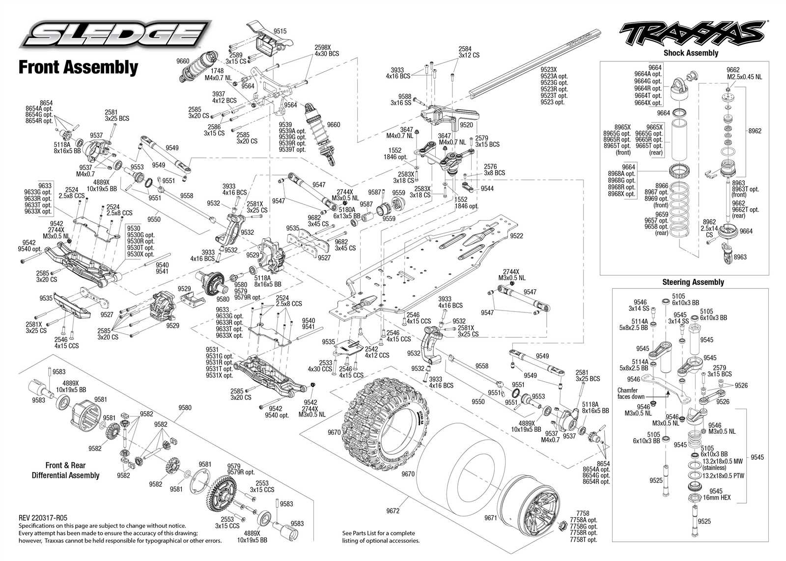
For those who prefer a hands-on approach, traditional drawing methods remain viable. Utilizing tools like tracing paper and colored pencils can yield visually appealing representations that emphasize specific elements. Incorporating annotations and arrows can guide the viewer’s eye, creating a narrative that is both informative and engaging. This method allows for personal expression while conveying essential information about the assembly process.
In summary, whether leveraging advanced software or traditional artistry, creating clear and informative representations of complex systems is crucial for effective communication. Adapting techniques to suit the intended audience can significantly enhance understanding and usability.
Common Mistakes to Avoid
When creating visual representations that break down components of a system, there are several pitfalls that can hinder clarity and effectiveness. Recognizing these errors is essential for ensuring that the final result communicates information accurately and efficiently.
Neglecting Clarity and Detail
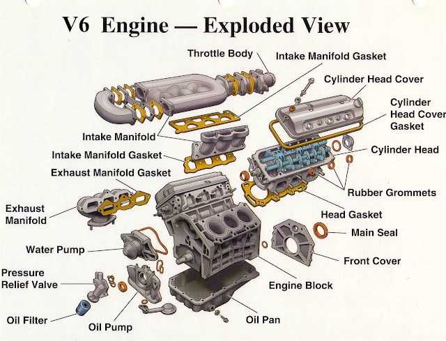
One of the most frequent issues is the failure to provide adequate detail. While simplicity is important, omitting critical information can lead to confusion. Ensure that every element is labeled clearly and that accompanying descriptions are comprehensive. This not only aids in understanding but also enhances the overall usability of the representation.
Overcomplicating the Design
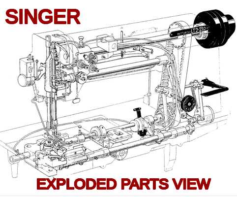
Another common mistake is creating an overly complex design. While it may be tempting to include numerous components, this can overwhelm the viewer. Strive for a balance between detail and simplicity. Focus on the most essential elements that convey the necessary information without cluttering the visual space. A clean, straightforward approach often yields the best results.
Tools and Software for Diagram Creation
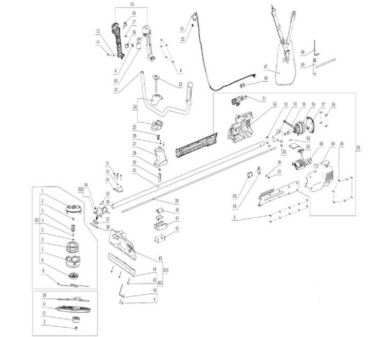
Creating detailed visual representations requires the right set of tools and applications to ensure clarity and precision. Various options exist that cater to different needs, whether for professional or educational purposes.
- Vector Graphic Software
- 3D Modeling Applications
- Online Diagramming Platforms
- CAD Software
Each of these categories offers unique features that can enhance the user experience and facilitate the creation of intricate layouts. Here are some popular choices:
- Lucidchart
- Microsoft Visio
- AutoCAD
- SketchUp
These tools allow users to visualize concepts effectively, making complex information accessible and understandable.
Future Trends in Diagram Visualization
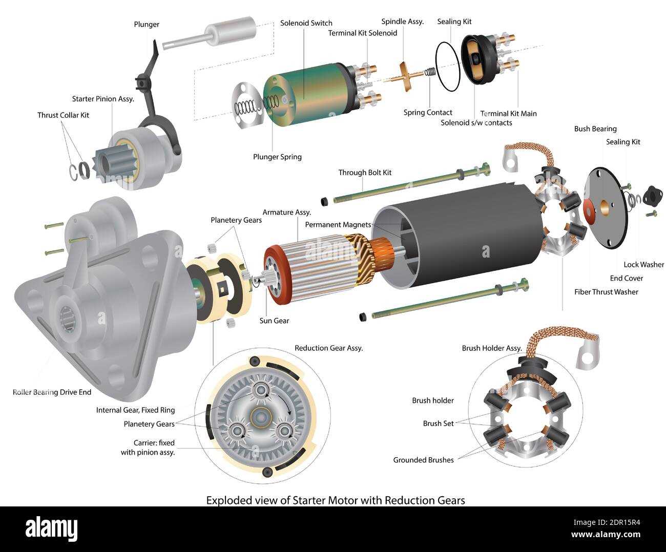
The evolution of visual representation techniques is set to transform how we interpret complex structures and systems. As technology advances, we are likely to witness a shift towards more interactive and immersive methods that enhance user engagement and understanding.
Augmented reality (AR) and virtual reality (VR) are poised to play a significant role in this transformation. These technologies enable users to explore three-dimensional models in a more intuitive manner, allowing for a deeper comprehension of intricate relationships and functionalities. By integrating sensory experiences, learners can interact with visual data in a way that traditional methods cannot offer.
Furthermore, the rise of artificial intelligence is expected to revolutionize the creation and customization of visual representations. AI-driven tools can analyze data patterns and automatically generate visual aids tailored to specific needs, ensuring that the information is not only relevant but also accessible. This personalization will facilitate a more efficient learning process and improve retention rates.
Collaboration tools are also evolving, allowing multiple users to interact with visual aids in real time. This fosters teamwork and shared understanding, particularly in remote environments. Enhanced communication through such platforms will lead to more effective problem-solving and decision-making.
In summary, the future of visual representation is bright, with advancements in technology promising to create more engaging, personalized, and collaborative experiences. Embracing these trends will be crucial for effectively conveying complex information across various fields.