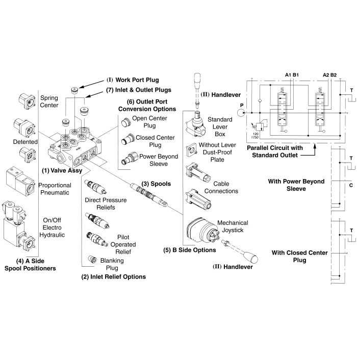
The intricate world of fluid control mechanisms plays a crucial role in various industrial applications. These systems are designed to manage the flow of liquids, ensuring efficiency and precision in operations. A comprehensive understanding of the individual elements that comprise these systems is essential for effective maintenance and troubleshooting.
Each component serves a specific function, contributing to the overall performance and reliability of the mechanism. By examining these elements, one can gain insights into their interactions and the principles governing their operation. This knowledge is invaluable for engineers and technicians alike, enabling them to optimize systems for enhanced functionality.
In this exploration, we will delve into the various elements involved, highlighting their design, roles, and how they work together to regulate the movement of fluids. Understanding these critical components not only aids in the effective operation of machinery but also empowers professionals to innovate and improve existing systems.
Understanding Cross Hydraulic Valves
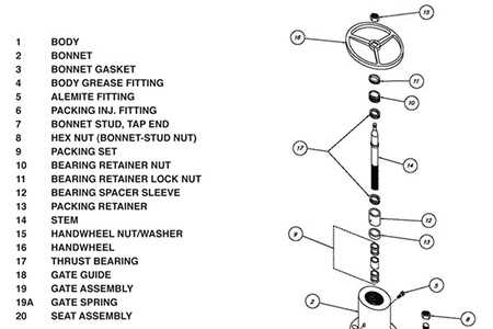
This section explores the essential mechanisms that facilitate fluid control in various applications, enhancing efficiency and functionality. By grasping the fundamental components, one can better appreciate how they operate in different systems.
- Functionality: These mechanisms manage the flow of fluids, ensuring precise operation.
- Components: Key elements include control units, actuators, and connectors, each playing a vital role.
- Applications: Widely used in machinery, automotive systems, and industrial equipment.
Understanding these systems provides valuable insights into their ultimate performance and reliability in diverse environments.
Key Components of Hydraulic Valves
Understanding the essential elements of fluid control mechanisms is crucial for anyone involved in systems that rely on fluid dynamics. These components work together to regulate flow and pressure, ensuring optimal performance and safety. Each piece plays a significant role in the overall functionality, contributing to the efficiency and reliability of the entire assembly.
| Component | Description |
|---|---|
| Actuator | Drives the mechanism that opens or closes the flow path. |
| Spool | Directs the fluid through various channels based on its position. |
| Body | Houses all internal components and provides structural integrity. |
| Spring | Returns the spool to its original position when the actuator is released. |
| Seals | Prevent leaks and ensure proper operation by maintaining pressure. |
Each of these components is designed with precision to ensure seamless interaction within the system. Their collective functionality is essential for achieving desired outcomes in various industrial applications.
Functionality of Cross Hydraulic Systems
The intricate design of certain control mechanisms plays a crucial role in optimizing performance across various applications. These systems are engineered to manage fluid movement, allowing for precise regulation and distribution of energy. Understanding their functionality is essential for enhancing efficiency and ensuring reliability in numerous industries.
Fluid Control Mechanisms
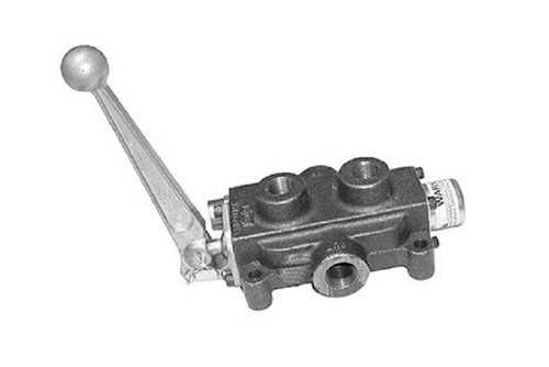
At the heart of these systems lies an array of components that govern the flow of liquids. By manipulating pressure and directing fluid streams, these mechanisms enable seamless transitions between different operational states. The ability to adjust parameters such as flow rate and pressure makes them indispensable in applications ranging from manufacturing to construction.
Importance of Design and Efficiency
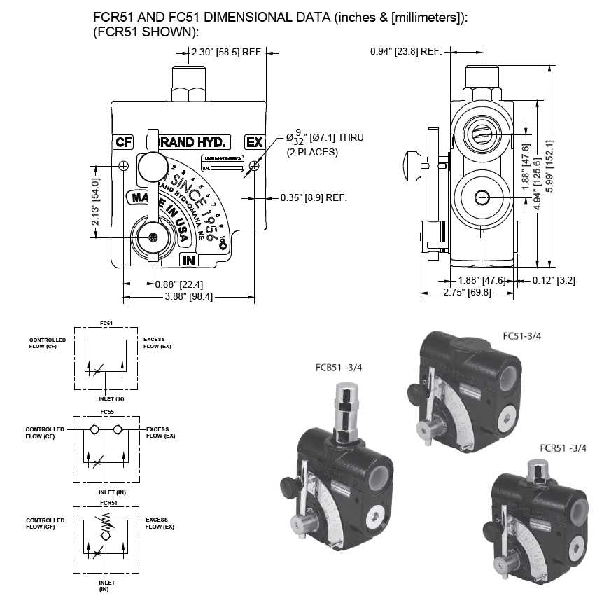
Effective design is paramount to achieving optimal functionality. Components must work harmoniously to minimize resistance and maximize output. Regular maintenance and timely adjustments ensure that these systems operate at peak efficiency, thereby extending their lifespan and reducing downtime. Understanding the nuances of these mechanisms can lead to significant advancements in both productivity and safety.
Common Applications for Hydraulic Valves
Fluid control mechanisms play a crucial role in various industries, enabling precise management of liquid flow and pressure. Their versatility allows for a wide range of uses across multiple sectors, enhancing efficiency and performance in machinery and systems.
Industrial Machinery
In manufacturing and heavy-duty equipment, fluid control elements are essential for ensuring optimal operation. Common applications include:
- Presses and stamping machines
- Excavators and loaders
- Injection molding machines
Automotive Sector
In vehicles, these devices are employed to manage braking systems and power steering. Key uses are:
- Brake assist systems
- Transmission control
- Suspension adjustments
These examples highlight the importance of fluid control devices in enhancing performance, safety, and efficiency across diverse applications.
Maintenance Tips for Hydraulic Parts
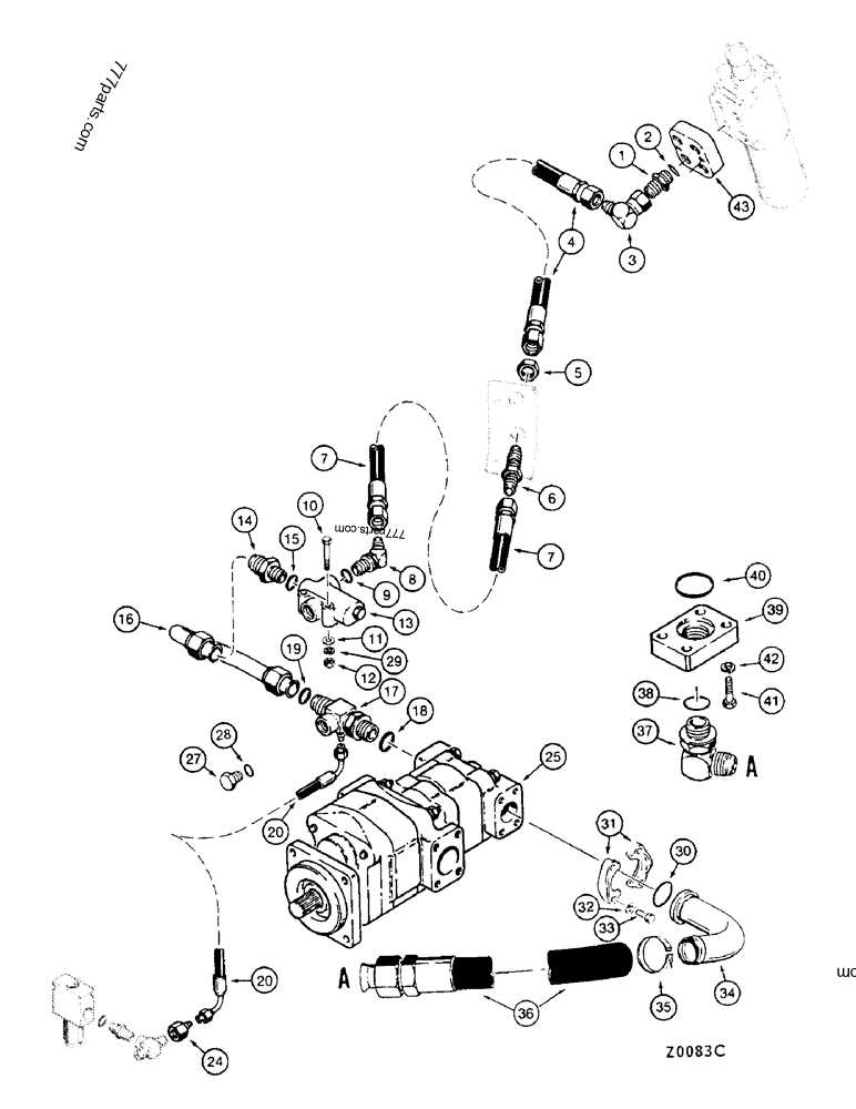
Ensuring the longevity and efficiency of essential components requires regular attention and care. Proper upkeep not only enhances performance but also prevents costly breakdowns. Here are key strategies to maintain these crucial elements.
Regular Inspection
- Conduct frequent visual checks for signs of wear or damage.
- Look for leaks that may indicate issues with seals or connections.
- Inspect the surrounding environment for contaminants that could affect functionality.
Routine Cleaning
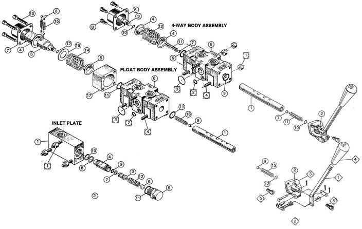
- Use appropriate solvents to clean surfaces without causing damage.
- Ensure all components are free of dirt and debris.
- Implement a cleaning schedule based on usage frequency and conditions.
Diagram Explanation of Valve Operation
This section provides a detailed overview of the mechanisms involved in the functioning of fluid control devices. Understanding these components and their interactions is crucial for effective system design and troubleshooting. The following explanation will clarify how each element contributes to the overall process.
Key Components
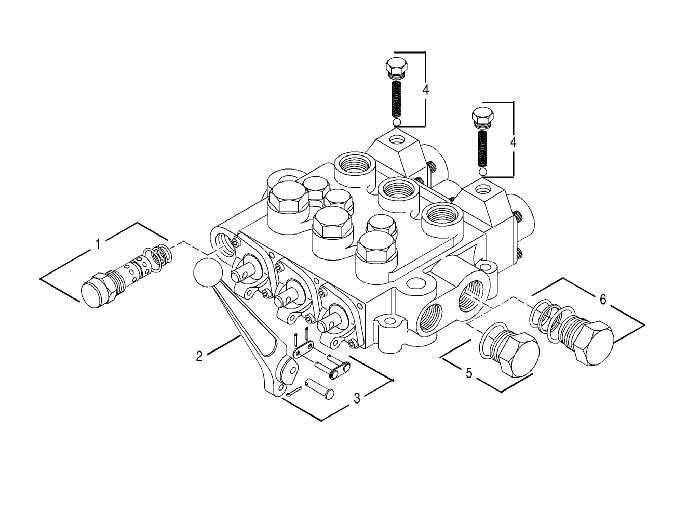
- Control Element: Regulates the flow direction and pressure.
- Actuator: Translates energy into mechanical movement.
- Spring Mechanism: Ensures return to default position when not engaged.
- Sealing Surface: Maintains the integrity of flow paths and prevents leaks.
Operational Principles
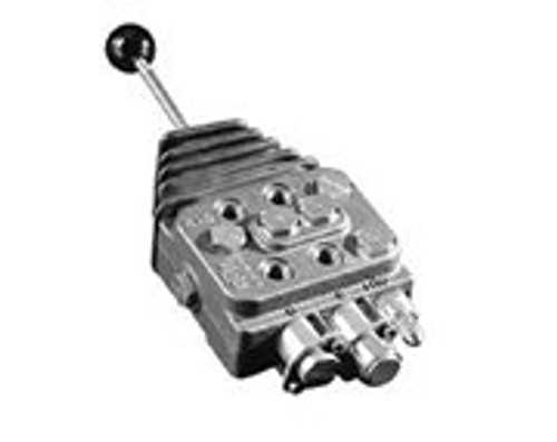
- The control element is initiated, allowing fluid to pass through designated pathways.
- As pressure builds, the actuator moves, influencing the position of the control element.
- The spring mechanism plays a vital role in restoring the system to its original state when pressure is released.
- Effective sealing ensures that the fluid remains contained within the system, preventing unwanted escape.
By examining these aspects, one can appreciate the intricate balance and functionality of these essential devices in fluid management systems.
Choosing the Right Hydraulic Valve
Selecting the appropriate control mechanism for fluid flow is crucial for optimal performance in various applications. The right choice can enhance efficiency, reliability, and overall functionality.
Here are some key considerations to help guide your decision:
- Application Requirements: Assess the specific needs of your system, including pressure, flow rate, and fluid type.
- Environmental Conditions: Consider factors such as temperature, exposure to elements, and potential contaminants.
- Control Type: Determine whether you need manual, pneumatic, or electronic operation.
- Size and Compatibility: Ensure that the selected mechanism fits within the existing system and meets space constraints.
- Durability and Maintenance: Look for options that offer longevity and ease of upkeep to minimize downtime.
By carefully evaluating these factors, you can delve into the selection process and identify the ultimate solution for your needs.
Impact of Valve Design on Performance
The configuration of flow control devices significantly influences their efficiency and functionality in various applications. Effective design ensures optimal operation and minimizes energy loss.
Key factors affecting performance include:
- Flow Rate: The shape and size of the passages directly impact how fluid moves through the system.
- Pressure Drop: An efficient layout reduces resistance, ensuring that pressure levels are maintained.
- Response Time: A well-designed mechanism allows for quicker actuation, enhancing overall responsiveness.
In summary, thoughtful engineering of these devices can lead to significant advancements in performance, efficiency, and reliability in various systems.
Future Trends in Hydraulic Technology
The evolution of fluid control systems is poised to undergo significant transformation, driven by advancements in engineering and innovative materials. These developments promise to enhance efficiency, reliability, and sustainability across various applications, from industrial machinery to automotive systems.
Smart Systems: Integration of digital technologies into fluid mechanisms is set to revolutionize operations. The implementation of sensors and IoT connectivity allows for real-time monitoring and predictive maintenance, reducing downtime and improving overall performance.
Energy Efficiency: As environmental concerns grow, the push for eco-friendly solutions becomes paramount. Future designs will focus on minimizing energy consumption, utilizing advanced materials that offer better performance with less environmental impact.
Miniaturization: The trend towards compact systems continues, allowing for more efficient use of space without sacrificing power or functionality. Smaller units can lead to lighter machinery and improved design flexibility, enhancing usability across various sectors.
Alternative Fluids: Research into biodegradable and non-toxic fluids is on the rise. These alternatives aim to reduce environmental risks associated with traditional fluids while maintaining performance standards, aligning with sustainability goals.
Automation: The increasing trend towards automated processes means that fluid control systems must adapt. The development of fully automated solutions that can respond dynamically to operational changes will be crucial in maximizing efficiency and minimizing human intervention.
In summary, the future of fluid control technology looks promising, with an emphasis on smart integration, energy efficiency, miniaturization, eco-friendly alternatives, and automation. These trends not only aim to enhance performance but also align with global sustainability efforts.