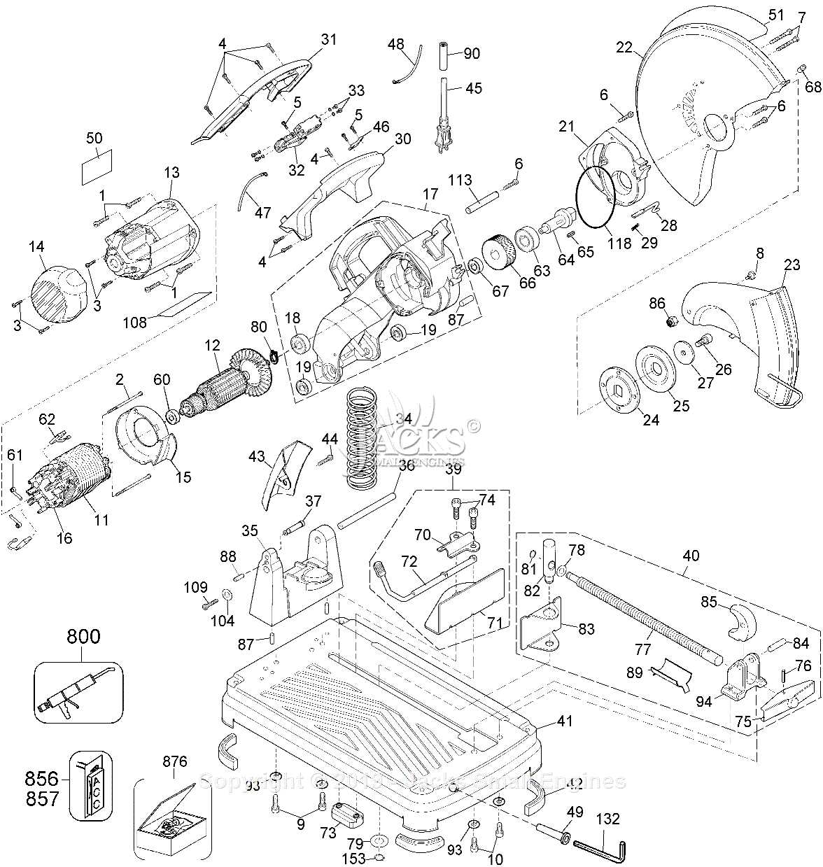
When working with power tools designed for accurate and efficient material cutting, it is essential to have a clear understanding of the various mechanisms involved. This overview explores the intricate elements that ensure precise performance, helping users identify key features that contribute to the tool’s functionality and longevity.
Each section of the device is carefully engineered to play a specific role in its operation. From the structure that provides stability to the elements responsible for delivering smooth cuts, every part is vital to the overall efficiency. Recognizing these components allows users to maintain their equipment and address any potential issues before they escalate.
This guide will walk you through the essential elements, offering insight into how each contributes to the performance of your cutting tool. Whether for maintenance, repair, or general knowledge, understanding these mechanical features can greatly enhance your experience with the device.
Understanding the Components of a Chop Saw
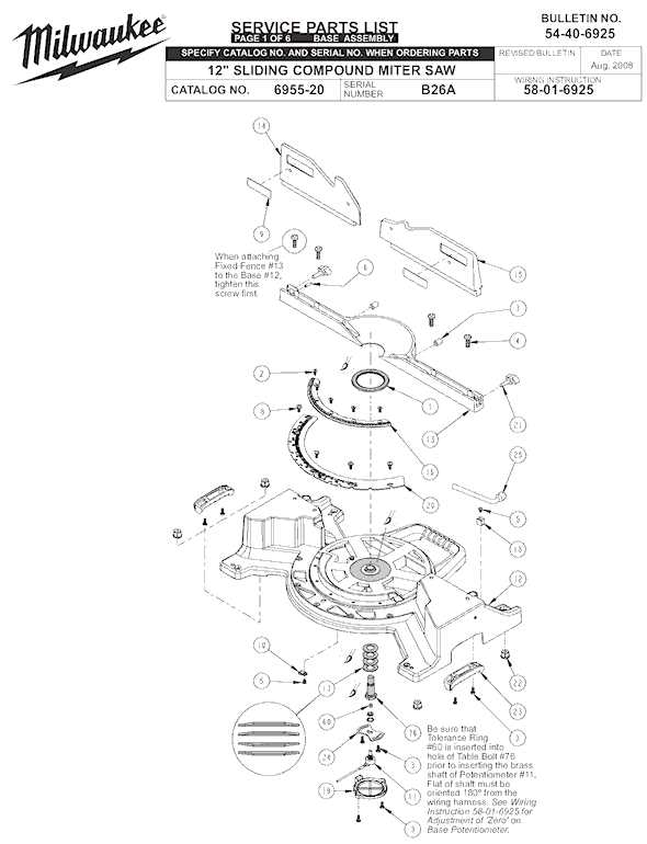
To operate a cutting tool efficiently, it is essential to familiarize oneself with its core elements. These features work together to ensure precision and safety during usage. By understanding how each component functions, users can maintain and utilize their tool more effectively.
- Motor: The driving force behind the device, responsible for powering the blade and determining cutting speed and performance.
- Blade Guard: A protective cover designed to minimize exposure to the rotating blade, ensuring safety during operation.
- Base: The foundation on which the material rests, providing stability and support while cutting.
- Fence: A guiding structure that helps to align the material for precise and straight cuts.
- Trigger: The mechanism that initiates the movement of the blade, allowing the user to
Main Body and Frame Design Features
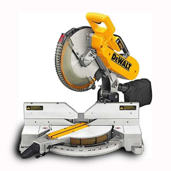
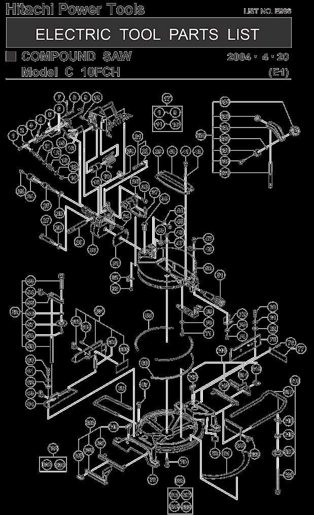
The core structure and support elements of the tool play a crucial role in ensuring stability and precision during operation. A well-engineered base and main framework provide the necessary foundation for seamless functionality, contributing to user safety and operational efficiency. These design elements are meticulously crafted to balance durability with ease of use, ensuring long-term performance and user satisfaction.
Frame Construction
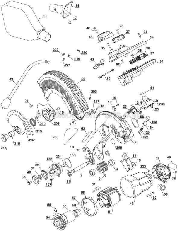
The frame is typically constructed from reinforced materials, offering both strength and resistance to wear. The choice of materials ensures that the tool can withstand heavy workloads while maintaining rigidity. Structural integrity is essential, as it minimizes vibration and enhances accuracy during operation.
Ergonomics and Usability
Designers pay close attention to ergonomics, making sure the main body is not only sturdy but also user-friendly. Grips, handles,
The Functionality of the Saw Blade
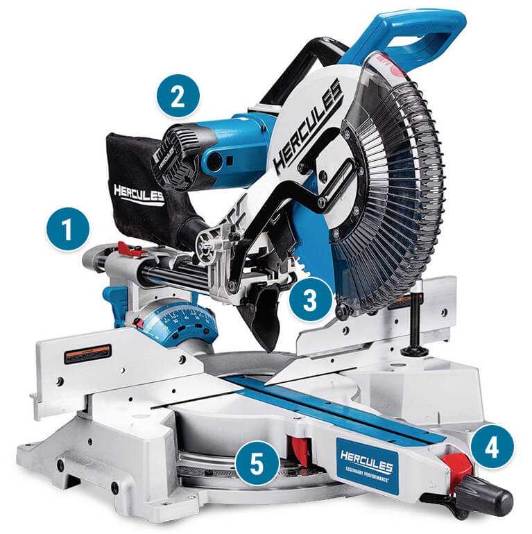
The blade plays a crucial role in cutting operations, determining both the efficiency and the precision of the task. Its design and material composition directly influence the quality of the cut, as well as the speed at which the work can be completed. Different types of blades are optimized for various materials, ensuring that the right tool is used for each specific job, whether working with wood, metal, or plastic.
The key factors that impact blade performance include the number of teeth, tooth design, and the overall shape. Below is a table summarizing the core elements that affect its functionality:
Feature Description Number of Teeth A higher tooth count results in finer cuts, while fewer teeth allow for faster material removal. Tooth Shape Motor Assembly and Its Importance
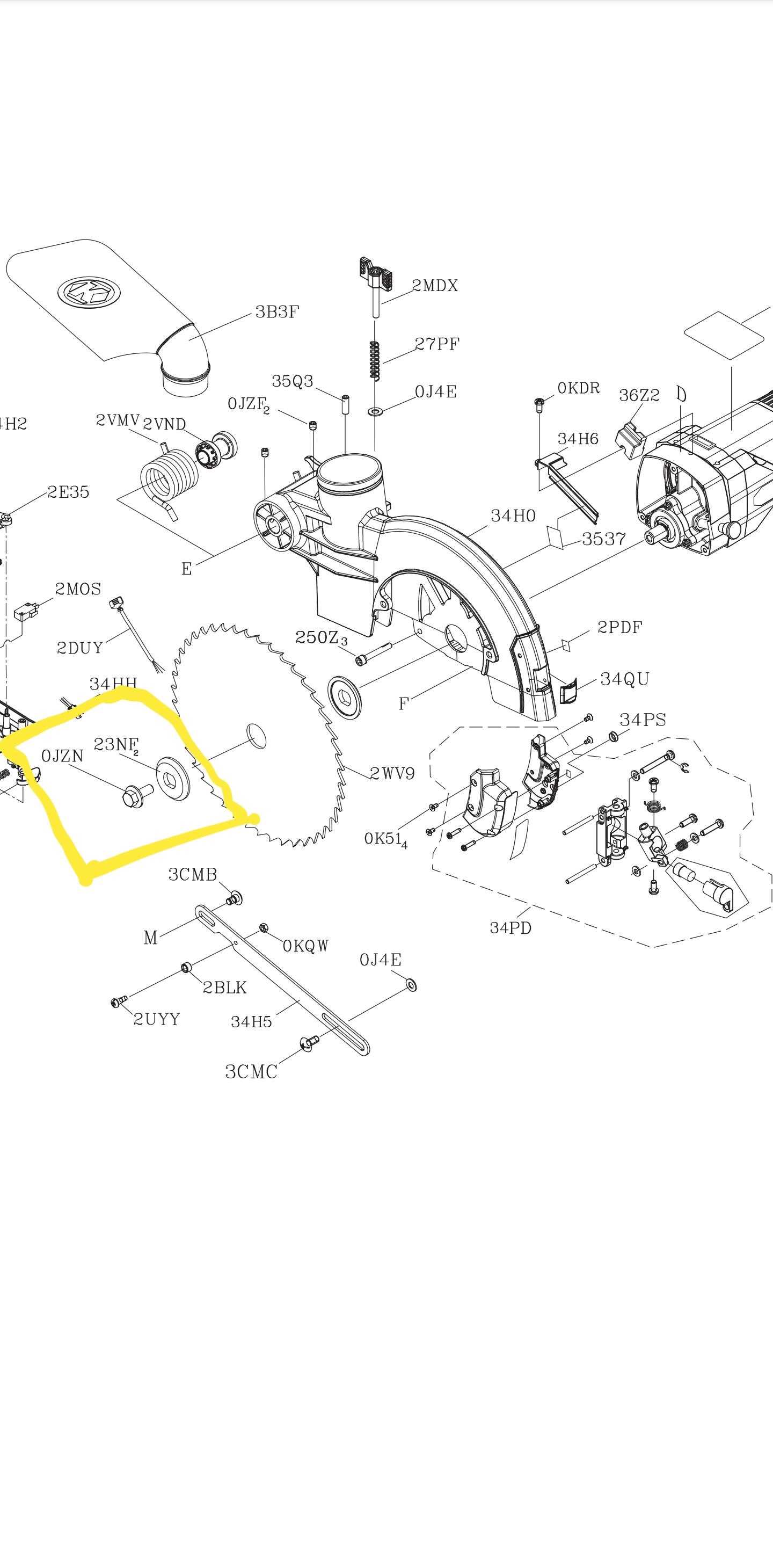
The motor assembly plays a vital role in the overall performance and functionality of any power-driven device. Without a well-integrated motor system, achieving precision, efficiency, and durability in mechanical tasks becomes significantly harder. This section explores how the motor unit contributes to the smooth operation and longevity of the equipment.
Proper understanding of the motor’s internal structure and its key components is essential for ensuring long-term reliability and optimal power output. The motor’s efficiency directly affects the device’s energy consumption and speed, making it a crucial factor for both performance and safety. Below is a table outlining the main components of a standard motor assembly:
Component Function Rotor Converts electrical energy into mechanical motion. Stator Provides the magnetic field necessary for rotor movement. Adjustable Fence Mechanism Overview 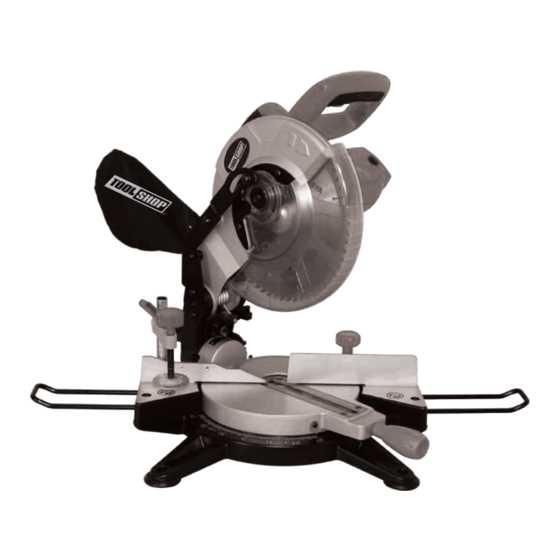
The adjustable fence mechanism is a crucial component designed to enhance precision and versatility in various cutting applications. It enables users to easily modify the cutting width, ensuring optimal results tailored to specific tasks.
This mechanism typically features several key elements:
- Sliding Rail: Allows for smooth movement and secure positioning.
- Locking Mechanism: Ensures stability during operation, preventing unwanted adjustments.
- Measurement Guide: Provides clear indicators for accurate settings.
Benefits of an adjustable fence include:
- Enhanced accuracy for precise cuts.
- Increased efficiency through quick adjustments.
- Versatility for different materials and project requirements.
Understanding this mechanism’s functionality can greatly improve operational effectiveness and overall user experience.
Explaining the Role of the Miter Gauge
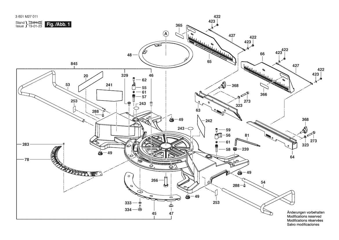
The miter gauge is an essential component used in woodworking equipment for making precise angled cuts. It provides stability and guidance for workpieces as they are pushed through the cutting mechanism, allowing for consistent accuracy in crosscuts and bevels. This tool helps achieve clean, angled cuts that are often necessary for projects involving frames, joints, or other intricate designs.
Precision in Angled Cuts
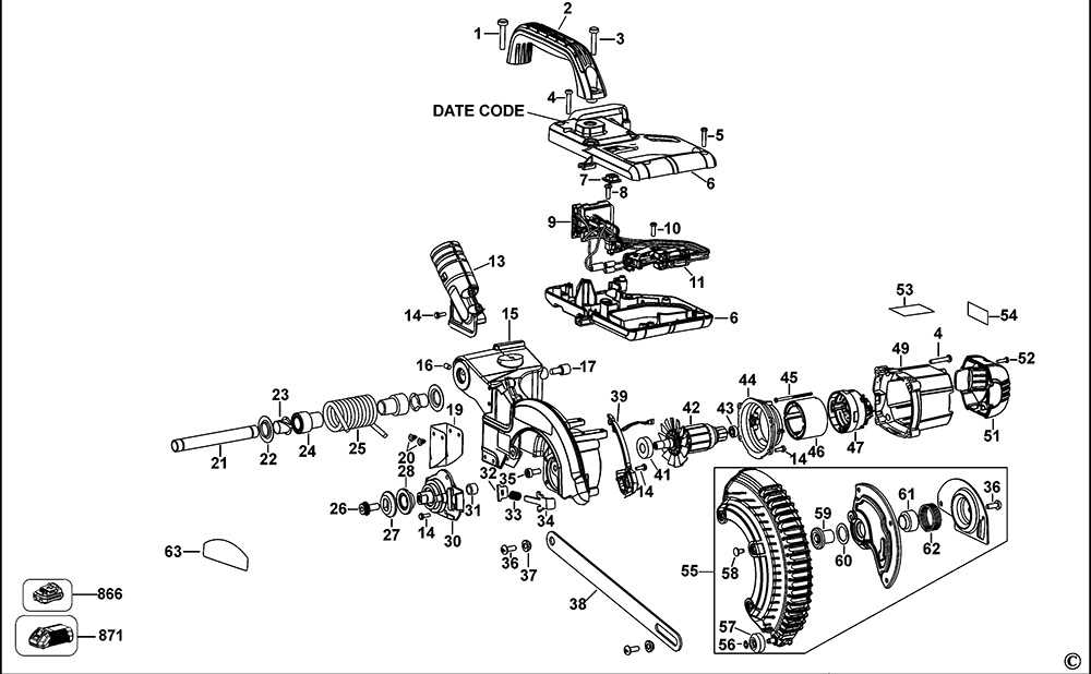
By holding the material at a specific angle to the cutting edge, the miter gauge allows woodworkers to execute accurate, repeatable cuts without the need for manual measurement. The adjustable nature of the tool enables easy modification of the cutting angle, enhancing the versatility of the equipment.
Improving Safety and Control
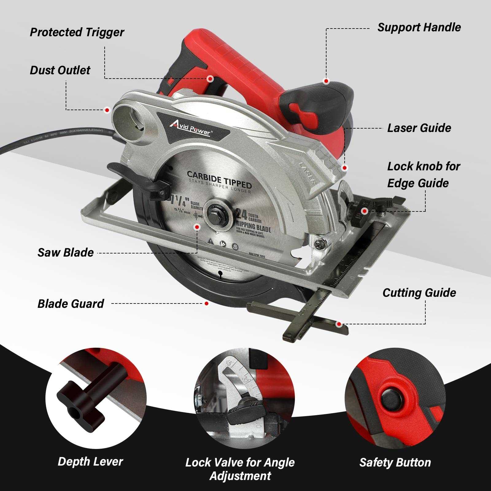
Beyond precision, the miter gauge also improves safety by keeping the hands away from the cutting path. The stable placement of the workpiece minimizes the risk of kickback or slipping, offering the user greater control and confidence when handling various materials.
Handle and Trigger Systems Explained
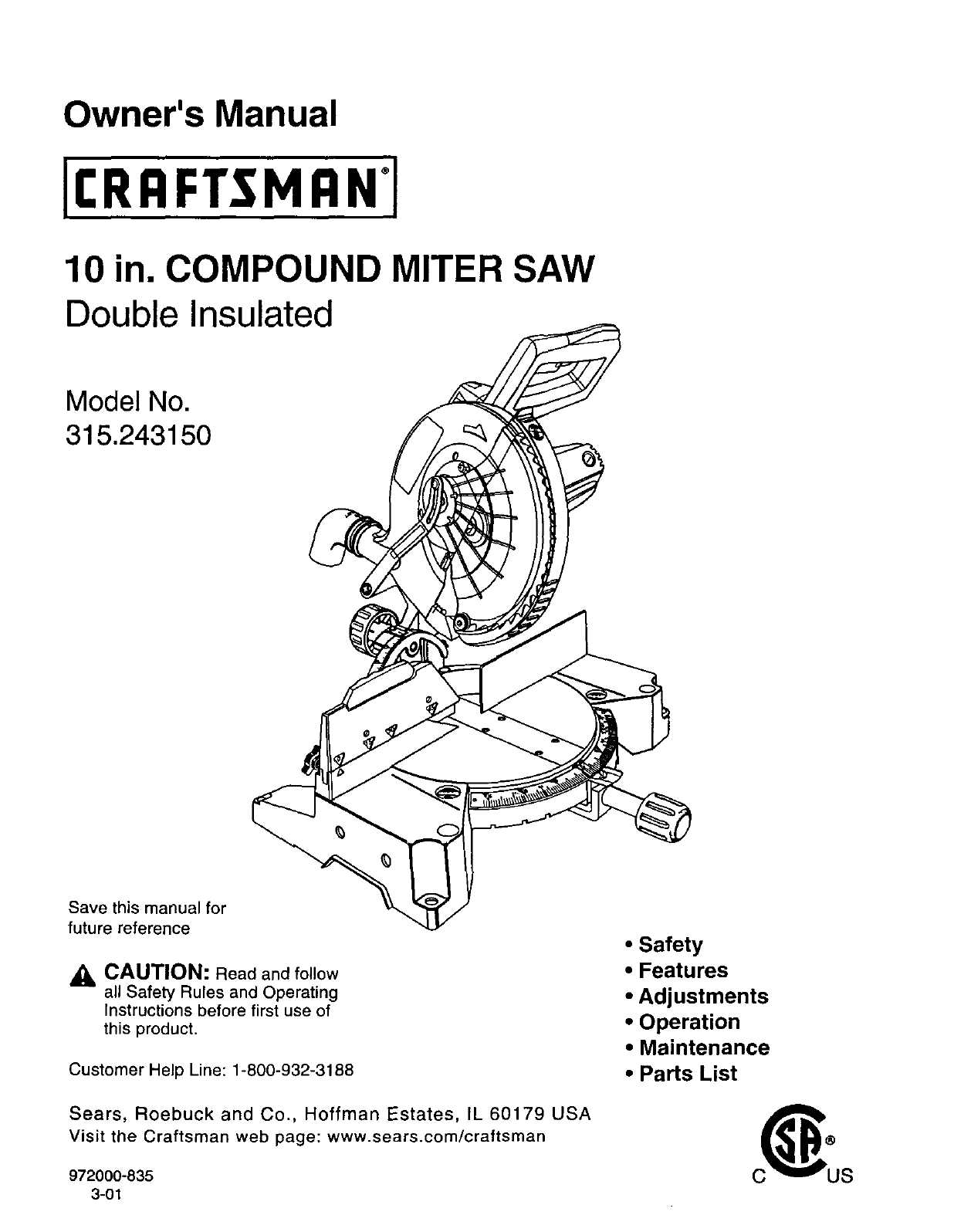
In cutting tools, the handle and trigger system plays a crucial role in ensuring both control and safety. These components provide the user with the necessary grip and functionality to operate the machine efficiently, while minimizing risks. Understanding how these systems work can help in maintaining smooth operation and extending the tool’s lifespan.
The handle typically serves as the main point of contact between the user and the tool. It is designed for ergonomic comfort, allowing the user to maintain a firm yet comfortable grip for extended periods. Additionally, the handle may be designed with anti-slip features to ensure safety during use, particularly when dealing with heavy-duty tasks.
- Handle Design: The shape and material of the handle play a significant role in user comfort and control. A well-designed handle helps reduce strain and fatigue.
- Trigger Mechanism: The trigger is often located within easy reach of the user’s hand. It controls the activation of the cutting mechanism, allowing for quick responses during operation.
- Safety Features: Many trigger systems incorporate a safety lock or secondary activation to prevent accidental start-ups, ensuring safe use at all times.
The interaction between the handle and trigger system ensures that the user can maintain optimal control over the machine while minimizing the risk of accidents. A reliable and well-constructed system can make a significant difference in the overall performance and safety of the equipment.
Guide to the Dust Collection System
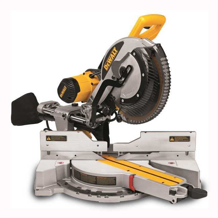
Effective management of debris and dust is essential when working with cutting machinery. A reliable dust collection setup helps maintain a clean workspace and ensures the proper functioning of your equipment. The system captures particles created during operation, minimizing their spread and reducing health hazards. This guide will explore how such a system functions and how to optimize it for efficient performance.
Understanding the System Components
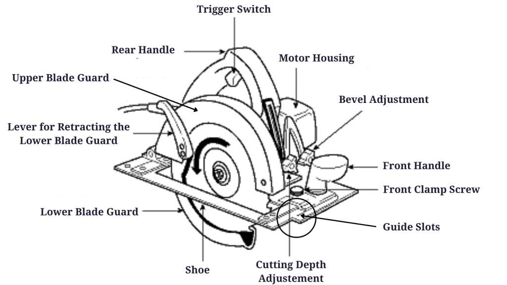
A typical dust collection system involves several key elements designed to trap and remove dust particles. The main components include the collection hood, hose or ductwork, and the collector itself. The system works by pulling dust away from the source, filtering it through a series of stages, and then expelling or storing it for disposal.
Maintaining Optimal Efficiency
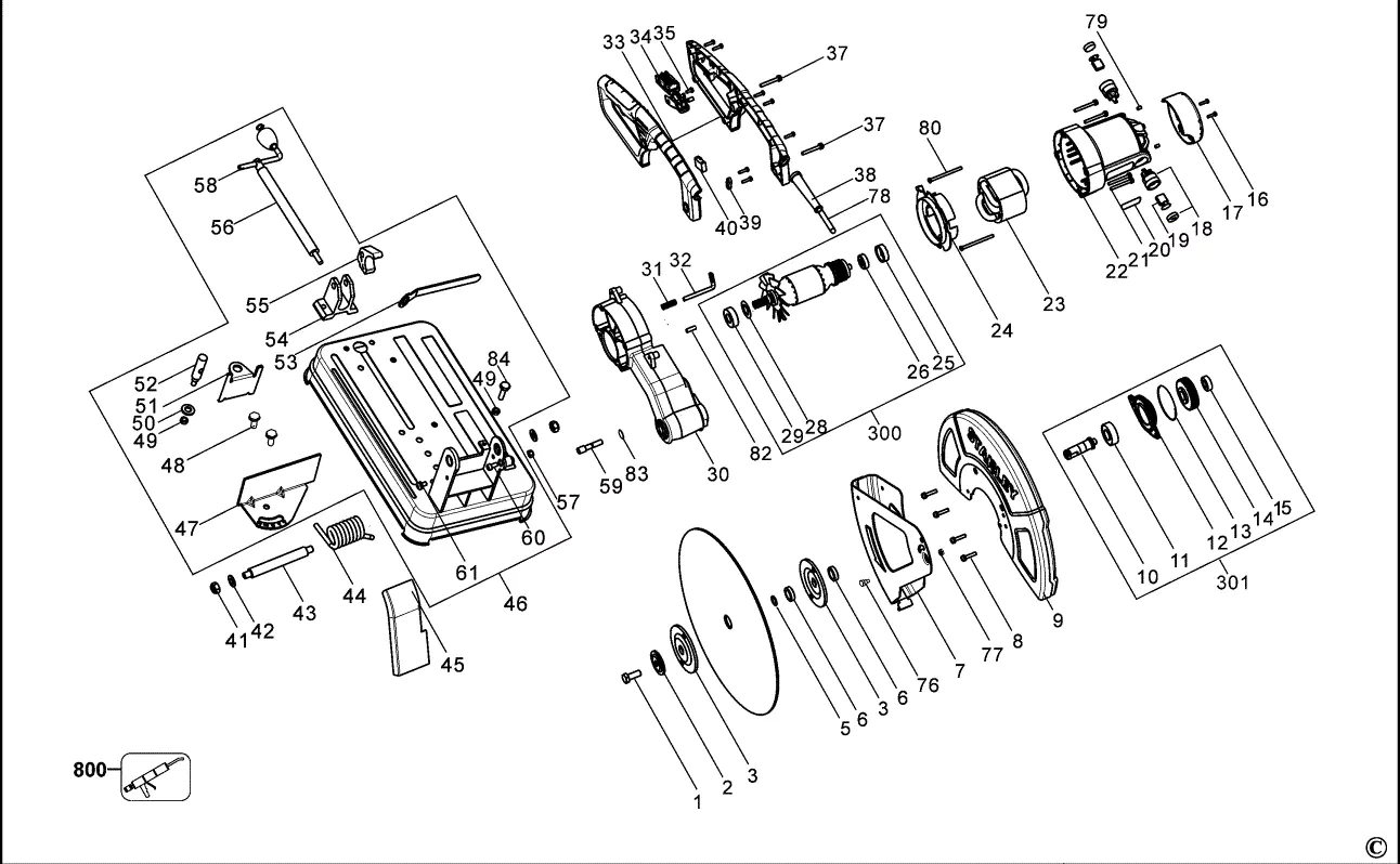
For maximum efficiency, it’s crucial to ensure that all parts of the system are in good condition. Regular maintenance, such as checking filters, inspecting hoses for blockages, and ensuring secure connections, helps avoid disruptions in performance. Additionally, positioning the collection hood close to the cutting area improves the system’s ability to capture dust at the source.
Component Function Collection Hood Captures dust as it is generated near the cutting tool. Ductwork Transports dust from the hood to the collector unit. Dust Collector Filters and stores the collected particles for disposal. How the Base and Supports Work Together
The foundation and supporting structures play a critical role in ensuring stability and precision during operations. Together, these components work to create a solid platform that accommodates the equipment’s movement and functions. The base provides a stable, flat surface, while the supports act as key stabilizers that reduce unwanted movement or vibrations, ensuring accurate performance during use.
These elements are designed to distribute weight evenly and maintain balance, which helps in reducing wear and tear over time. Without proper alignment between the base and supports, the equipment may experience issues such as misalignment or instability, affecting overall performance and safety.
Component Function Base Provides a stable foundation for all movements and operations. Supports Stabilizes and reinforces the base, reducing vibrations and ensuring accuracy. Connection Points Facilitate the proper attachment of the supports to the base, ensuring balance and secure positioning.