
The structure and arrangement of essential mechanical elements in the MP 54 model provide crucial insights into its functionality. Understanding the layout of various components ensures efficient maintenance and operation, especially for those looking to optimize performance or troubleshoot potential issues.
Each section within the equipment has its own distinct set of features, offering unique roles in the overall system. A clear understanding of how these elements are interconnected helps in enhancing the longevity and reliability of the machinery. This guide focuses on providing a detailed view of the internal configuration.
Whether you are repairing or performing routine inspections, having a clear visualization of the equipment’s layout is invaluable. In the following sections, we will delve deeper into the specific arrangement of each major element, ensuring a thorough comprehension of the system’s design.
Big Dog Alpha MP 54 Maintenance Guide
Proper upkeep is essential for ensuring the long-lasting performance of your machine. Regular care can prevent unexpected issues and prolong the life of key components. By following a few simple steps, you can keep your equipment running smoothly and efficiently.
Regular Cleaning
Maintaining a clean surface not only improves the appearance of your device but also ensures that no debris interferes with its operation. Be sure to clean all exposed areas regularly, removing dirt, grass, and other residues that may accumulate over time.
Lubrication and Fluid Checks
Ensuring that all moving parts are well-lubricated is vital for the smooth operation of your machine. Additionally, regularly check the fluid levels to ensure optimal performance. Keeping these elements in check helps prevent wear and tear on crucial components.
Understanding the MP 54 Mower Deck
The MP 54 mower deck is a crucial component designed to deliver efficient cutting performance across various terrains. By examining the structure and key features, users can gain a deeper understanding of how this deck contributes to the overall mowing efficiency.
The mower deck is composed of several essential elements that work together to ensure smooth operation. Each of these parts plays a specific role in maintaining the machine’s cutting precision.
- Blades: Responsible for cutting grass evenly, these sharp tools must be regularly inspected for wear and damage.
- Spindle assembly: This mechanism connects the blades to the mower, enabling the blades to rotate and perform their task.
- Deck shell: The main housing of the deck, providing protection and support for the internal components.
- Belt system: Transfers power from the engine to the blades, ensuring they spin at the right speed for effective cutting.
- Anti-scalp wheels: Help the deck glide over uneven surfaces, preventing the blades from cutting too close to the ground.
Key Components of the Drive System
The drive system is a crucial element in ensuring smooth and efficient operation. It consists of several interconnected elements that work together to provide power and motion. Understanding these components is essential for maintaining and troubleshooting the equipment.
- Transmission – The mechanism responsible for transferring energy from the motor to the wheels or other moving parts.
- Clutch – This part allows for the engagement or disengagement of power, providing control over movement and stopping.
- Belts and Chains – Used to connect different moving parts, ensuring the proper transmission of force throughout the system.
- Drive Shaft – A critical element that transmits rotational power from the engine to other components in the system.
- Axle – Supports the weight and transmits the force needed to move the machinery forward.
Each of these compo
How to Identify Engine Parts
Understanding the various components of an engine is crucial for proper maintenance and repair. Identifying these components can help in troubleshooting issues and ensuring the engine runs smoothly. Below are some tips to help you recognize different sections of an engine without confusion.
- Start by locating the central component that drives the mechanical power–often the core of the system.
- Next, observe the surrounding elements that manage fuel delivery and air intake.
- Look for the sections responsible for cooling, as these are vital to prevent overheating.
- Pay attention to the structure that handles exhaust gases, ensuring they exit the engine properly.
By familiarizing yourself with these major areas, you can confidently identify essential elements of an engine and address potential issues more effectively.
Electrical System Overview and Diagrams
The electrical system of the machine plays a critical role in ensuring proper functionality and efficiency. It consists of interconnected circuits, components, and control units that manage power distribution throughout the equipment. This section will provide a clear understanding of how the electrical system operates, covering key aspects such as wiring, connections, and the role of various electrical elements.
Main Components of the Electrical System
The electrical system includes several essential components, such as the ignition system, battery, alternator, and fuse box. These components work in unison to power various functions, from engine startup to controlling lights and other accessories. Proper maintenance and understanding of these elements are crucial for smooth operation.
Wiring and Circuit Layout
The wiring network is an integral part of the electrical system, responsible for transmitting power to different areas of the equipment. The layout of circuits is designed to ensure that each part receives the necessary voltage and current. A well-organized wiring structure also helps in troubleshooting and diagnosing any electrical issues that may arise during operation.
Blade Assembly and Replacement Instructions

This section provides essential guidance for assembling and replacing the cutting mechanism of your equipment. Proper maintenance of this component is crucial for ensuring optimal performance and longevity. Following the outlined steps will help you successfully manage the assembly process and facilitate a smooth replacement when necessary.
Assembly Steps
To assemble the cutting element, adhere to the following sequence:
- Begin by gathering all necessary tools and components.
- Align the cutting edge with the mounting brackets on the main unit.
- Secure the cutting edge in place using the provided fasteners, ensuring a tight fit.
- Double-check the alignment and stability of the assembly before proceeding.
Replacement Procedure
When it comes time to replace the cutting element, follow these steps for effective execution:
- Turn off the equipment and disconnect it from the power source.
- Remove the existing cutting edge by loosening the fasteners.
- Carefully detach the worn component and dispose of it appropriately.
- Install the new cutting edge using the assembly steps outlined above.
| Tool | Purpose |
|---|---|
| Wrench | For tightening and loosening fasteners |
| Safety Goggles | To protect eyes during assembly and maintenance |
| Replacement Blade | To ensure effective cutting performance |
Steering System Breakdown for Repairs
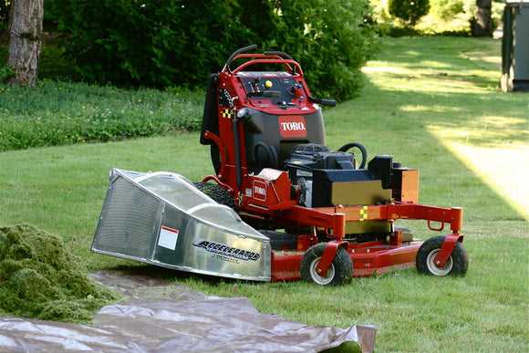
The steering mechanism plays a crucial role in the overall functionality and safety of a vehicle. Understanding its components and their interactions is essential for effective troubleshooting and maintenance. This section provides an overview of the key elements involved in the steering system, aiding in the identification of issues that may arise during operation.
Typically, the steering assembly comprises various crucial components, including the steering wheel, shaft, and gear system. Each of these elements must work seamlessly together to ensure smooth maneuverability. Regular inspections and maintenance can prevent potential malfunctions and extend the lifespan of the entire system.
When addressing steering issues, it is vital to evaluate the alignment of the wheels, as misalignment can lead to excessive tire wear and affect handling. Additionally, checking the fluid levels in the steering reservoir is important, as low fluid can result in stiffness or difficulty in steering. By conducting thorough evaluations and timely repairs, the steering system can remain in optimal condition.
Safety Features and Part Locations
This section explores the essential safety mechanisms integrated into the model, emphasizing their significance in ensuring secure operation. Understanding where these features are located enhances user familiarity and promotes effective maintenance practices.
Key Safety Mechanisms
The unit incorporates several vital safety elements designed to minimize risks during usage. These include emergency shut-off systems, protective guards, and stability features. Each component plays a crucial role in safeguarding the user and prolonging the lifespan of the equipment.
Component Placement
Recognizing the locations of these safety features is imperative for proper handling and troubleshooting. Typically, emergency shut-off switches are strategically positioned within easy reach of the operator, while protective guards are mounted around moving parts to prevent accidental contact. A thorough understanding of these placements can significantly enhance operational safety.
Common Issues with Hydraulic Components
Hydraulic systems are vital in numerous applications, providing power and precision through fluid movement. However, like any mechanical system, they can encounter various challenges that may affect performance and efficiency. Understanding these common issues is essential for effective maintenance and operation.
One frequent problem involves leaks, which can occur due to wear and tear on seals and fittings. These leaks not only lead to fluid loss but can also compromise the system’s overall effectiveness. Regular inspections can help identify and address these leaks promptly.
Contamination of hydraulic fluid is another significant concern. Dirt, debris, or water can enter the system, causing damage to components and reducing efficiency. Implementing proper filtration systems and routine fluid changes can mitigate this risk.
Moreover, cavitation is a phenomenon that can arise when fluid pressure drops below vapor pressure, leading to the formation of bubbles that can damage pumps and valves. Monitoring system pressure and ensuring that the system operates within recommended parameters is crucial to preventing cavitation.
Lastly, overheating can occur when fluid temperatures exceed optimal levels, often due to excessive demand or inadequate cooling. This can lead to a breakdown of hydraulic fluid and damage to components. Regular temperature monitoring and ensuring adequate cooling systems can help maintain ideal operating conditions.