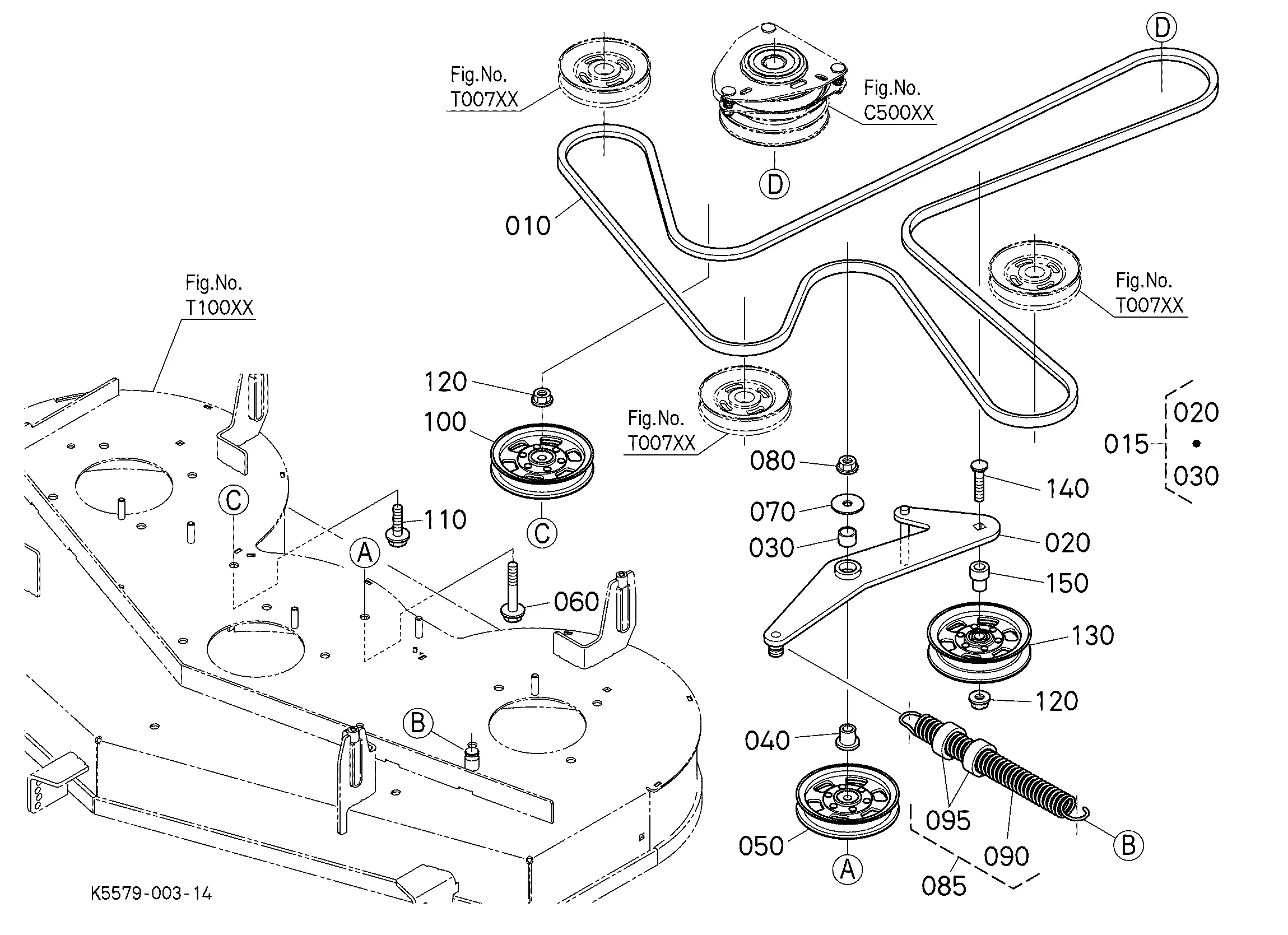
The intricate assembly of agricultural machinery plays a crucial role in its overall functionality and efficiency. A comprehensive understanding of how various elements are arranged can significantly enhance maintenance and repair processes. By examining these layouts, users can gain insights into the relationships between different components, allowing for more effective troubleshooting and enhancements.
For those involved in the upkeep of farming equipment, having access to detailed schematics is essential. Such visual guides not only simplify the identification of specific components but also facilitate informed decision-making when it comes to repairs or replacements. This knowledge is invaluable for both novice and experienced operators aiming to optimize their machinery’s performance.
In the realm of agricultural tools, clarity and precision in understanding how each part interacts contribute to the longevity and reliability of the equipment. By exploring various layouts, one can uncover the intricacies of design and functionality, ensuring that every component works harmoniously towards achieving operational excellence.
Overview of John Deere 130 Components
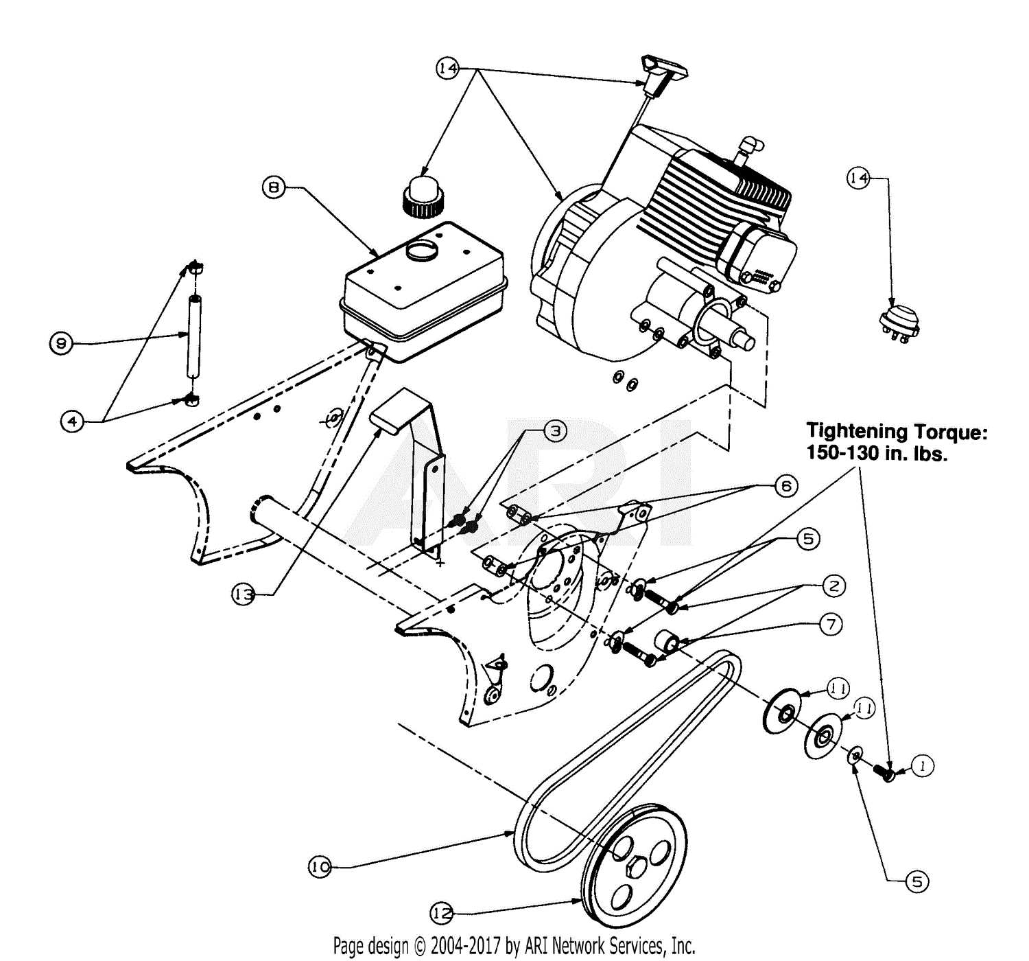
This section provides a comprehensive examination of the various elements that make up the machinery. Understanding these components is crucial for effective maintenance and optimal performance.
| Component | Description |
|---|---|
| Engine | Power source that drives the entire unit. |
| Transmission | System responsible for transferring power from the engine to the wheels. |
| Chassis | Framework that supports the various systems and provides structural integrity. |
| Hydraulics | Mechanism that allows for lifting and operating attachments. |
| Electrical System | Network that powers lights, sensors, and ignition. |
Key Systems in John Deere 130
This section explores the essential components that contribute to the efficient operation of this agricultural equipment. Each system plays a critical role in ensuring functionality and performance, impacting overall productivity in various tasks.
Powertrain System
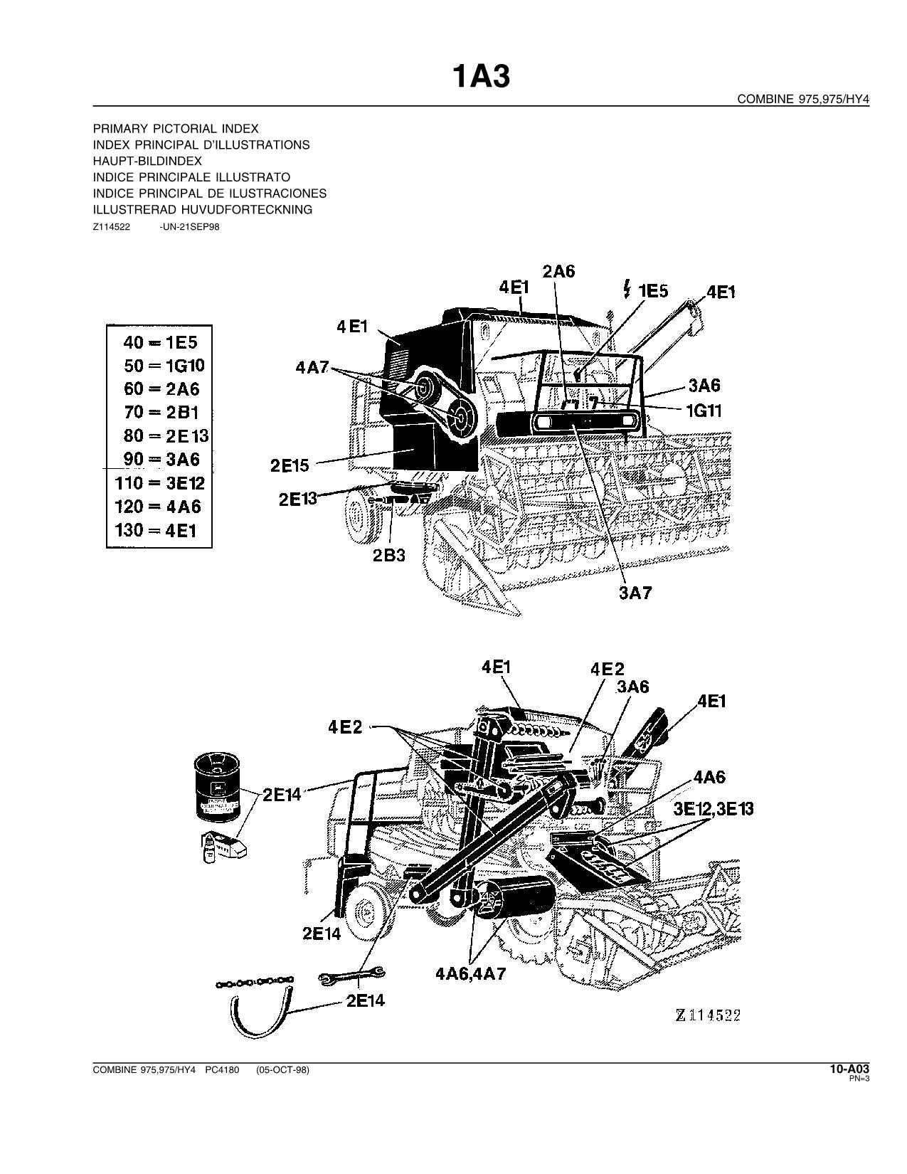
The powertrain is vital for the movement and operation of machinery. Key elements include:
- Engine: Provides the necessary power for operation.
- Transmission: Facilitates speed changes and torque delivery.
- Drive Shafts: Transmit power from the engine to the wheels.
Hydraulic System
This system enhances the machine’s capabilities, allowing for various attachments and tools to be used effectively. Key components include:
- Hydraulic Pump: Generates flow and pressure for the system.
- Hydraulic Cylinders: Convert hydraulic energy into mechanical force.
- Valves: Control the direction and flow of hydraulic fluid.
Understanding these systems is crucial for maintenance and efficient operation, ensuring longevity and reliability in field tasks.
Engine Parts Breakdown for John Deere 130
This section provides an in-depth exploration of the essential components that make up the engine system of the specified model. Understanding these elements is crucial for effective maintenance and optimal performance. Each part plays a significant role in the overall functionality and efficiency of the machinery.
Key Components Overview
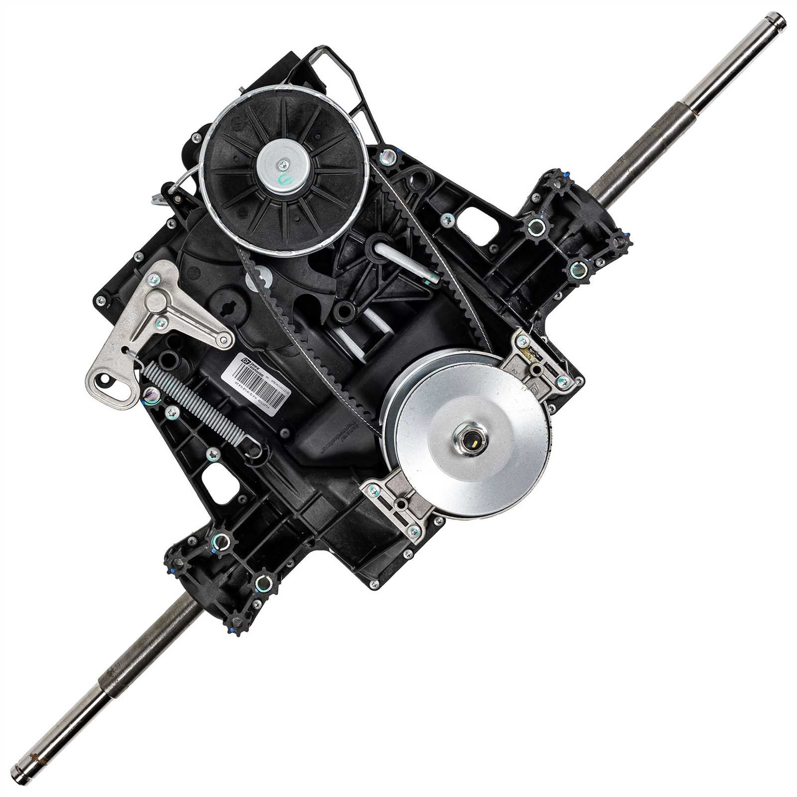
Among the vital elements are the cylinders, which facilitate the combustion process, and the piston, responsible for converting pressure into mechanical energy. Additionally, the valve train manages the intake and exhaust of gases, ensuring smooth operation.
Maintenance Tips
Regular checks on the fuel system and cooling system are essential to prevent overheating and ensure efficient fuel usage. Keeping these components in top condition contributes significantly to the longevity and reliability of the engine.
Understanding the Transmission Assembly
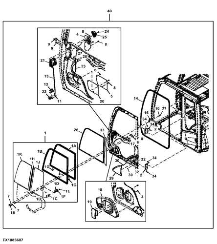
The transmission assembly plays a crucial role in the functionality of various machinery, enabling the effective transfer of power from the engine to the wheels. This intricate system consists of multiple components that work together to ensure smooth operation and optimal performance.
Components within the assembly include gears, shafts, and clutches, each designed to handle specific functions. These elements interact harmoniously, allowing for adjustments in speed and torque as needed. Understanding these parts is essential for diagnosing issues and maintaining efficiency.
Proper maintenance of the transmission assembly can significantly enhance the lifespan of the equipment. Regular checks and timely replacements of worn components can prevent costly breakdowns and ensure reliable operation.
Steering Mechanism and Control Elements
The steering system plays a crucial role in maneuverability and operator control in agricultural machinery. Understanding its components and functionality is essential for effective handling and performance optimization.
Key Components
Central to the steering mechanism are the linkages and gear assemblies, which translate the operator’s input into directional movement. These elements work together to provide smooth and responsive steering, ensuring precise control over the vehicle’s trajectory.
Operational Mechanism
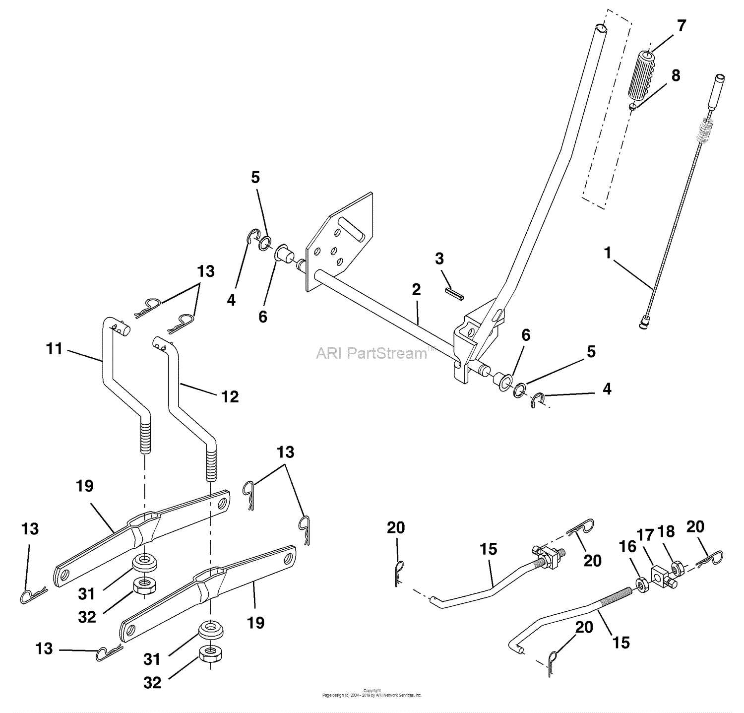
The control elements, including steering wheels and pedals, facilitate user interaction with the system. By delving into the intricacies of this operational framework, one can appreciate the ultimate efficiency and effectiveness of the machinery in various agricultural tasks.
Exploring the Electrical System Layout
The electrical system is a vital component that ensures the efficient operation of machinery. Understanding its configuration can significantly enhance maintenance and troubleshooting efforts. A well-organized electrical framework not only facilitates smoother functioning but also aids in identifying potential issues before they escalate.
Furthermore, an overview of safety measures and best practices when working with electrical systems will be provided. Familiarizing oneself with these guidelines is crucial for preventing accidents and ensuring the longevity of the equipment. By mastering the layout of the electrical configuration, operators can ensure their machinery remains in peak condition.
Hydraulic Components and Connections
The hydraulic system of agricultural machinery is vital for efficient operation, relying on a network of elements that work in harmony. These components ensure that power is effectively transmitted through the machine, enabling various functions such as lifting, steering, and tilting.
Key elements include hydraulic pumps, cylinders, and valves, each serving a specific role in the system. The pumps generate fluid pressure, while cylinders convert this pressure into mechanical force. Valves manage the flow of fluid, directing it to different parts of the machinery as needed.
Understanding the connections between these components is essential for maintenance and troubleshooting. Properly aligned hoses and fittings prevent leaks and ensure optimal performance, contributing to the ultimate efficiency of the entire system.
Chassis and Frame Structure Analysis
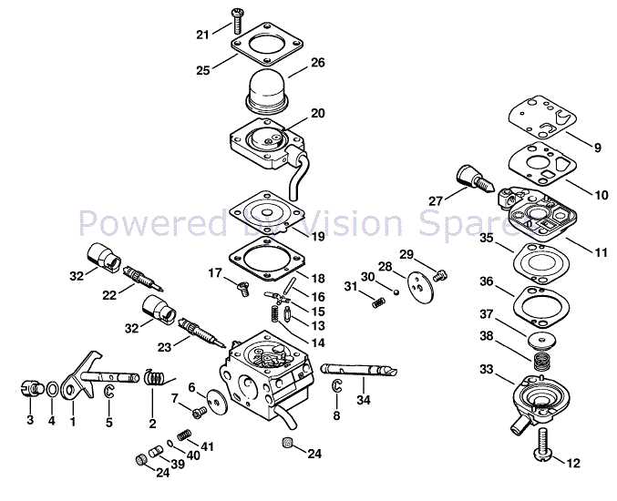
The chassis serves as the foundational framework that supports various components of machinery, ensuring stability and strength during operation. A thorough examination of this structure reveals its critical role in distributing loads and absorbing stresses, ultimately affecting the overall performance and durability of the equipment.
Frame Integrity is paramount for the longevity and reliability of any machine. The design incorporates robust materials that withstand significant forces, while innovative engineering techniques enhance rigidity and resilience. This framework must balance weight with strength, ensuring efficient functionality without compromising structural integrity.
Component Interconnection is another vital aspect of the chassis. Each section must seamlessly integrate with other parts, providing not only support but also facilitating movement and operation. Proper alignment and secure fastening contribute to the machine’s ability to perform under various conditions, preventing misalignments that could lead to failures.
Finally, understanding the maintenance requirements of the frame structure is essential. Regular inspections and timely repairs can extend the lifespan of the chassis, ensuring optimal performance throughout its operational life. By prioritizing this aspect, operators can avoid costly downtimes and enhance productivity.
Maintenance Tips for Key Parts
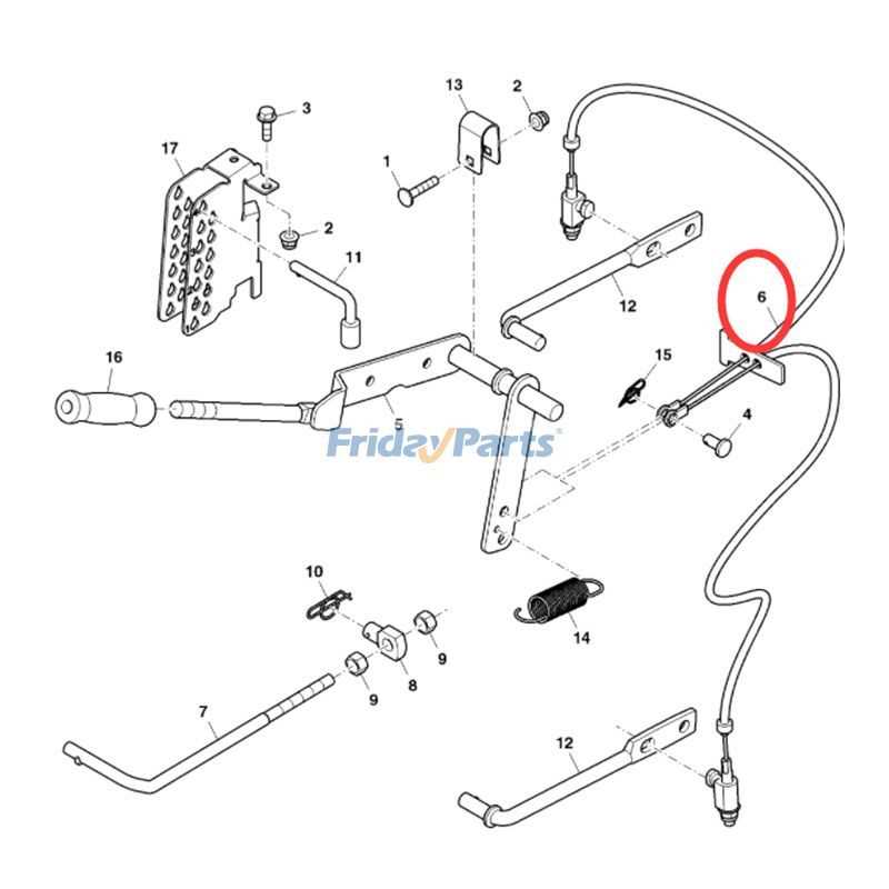
Regular upkeep of essential components is crucial for ensuring optimal performance and longevity of your machinery. By focusing on specific areas, operators can prevent common issues, enhance efficiency, and reduce downtime. Here are some practical suggestions to keep in mind during maintenance routines.
Lubrication and Cleaning
Consistent lubrication of moving elements is vital to minimize friction and wear. Use appropriate lubricants recommended for your equipment, applying them at regular intervals. Additionally, keep surfaces clean from dirt and debris to prevent buildup that could lead to malfunction.
Inspection and Replacement
Conduct thorough inspections of critical components to identify any signs of wear or damage. Replace worn-out parts promptly to avoid potential failures. Regular checks of belts, filters, and seals can save time and resources by addressing issues before they escalate.