Case 580 Super M Parts Diagram Overview

In case

case 580 super m parts diagram

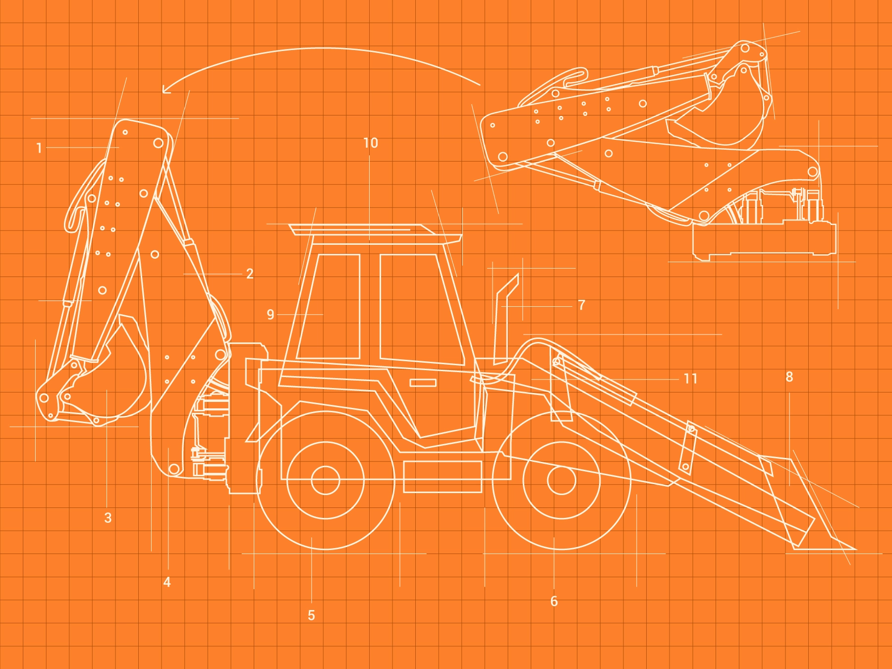
The inner workings of heavy-duty machinery require a deep understanding of its essential elements. This model, known for its reliability in tough working conditions, is composed of numerous interconnected components that work in harmony to ensure smooth operation. Understanding how each part functions within the whole system is crucial for maintenance and repair.

Each section of the machine is designed with precision, ensuring durability and optimal performance. Whether focusing on the engine, hydraulic systems, or control mechanisms, every component plays a vital role in its overall efficiency. Regular inspections and familiarity with the arrangement of these elements can significantly extend the lifespan of the equipment.

Having a clear visualization of these mechanical parts helps operators and technicians identify issues quickly, making it easier to perform necessary adjustments or replacements. Familiarity with the model’s structure ensures that any potential downtime is minimized, keeping productivity levels high.

Understanding the Key Components of the Case 580 Super M
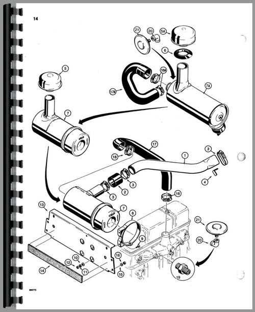
case 580 super m parts diagram

The equipment under discussion is a versatile machine designed for various heavy-duty tasks. To fully grasp its functionality, it’s essential to examine the crucial elements that work together to deliver its high performance. Each component plays a significant role in ensuring that the machine operates efficiently, providing both power and precision in its operations.

Exploring the Engine System Layout

The engine system is a crucial component of any construction machinery, ensuring optimal performance and reliability. Understanding the layout of this system can help users maintain, troubleshoot, and operate the machinery more efficiently. This section delves into the essential elements that make up the engine system, focusing on the relationship between different mechanical parts and how they interact to provide power and functionality.

Main Components of the Engine

case 580 super m parts diagram

  • Power Source: The engine itself generates the necessary force to drive various mechanical systems.
  • Cooling Mechanism: This section includes fans, radiators, and other devices designed to manage temperature levels during operation.
  • Fuel System: Comprising fuel injectors, pumps, and lines, it ensures a steady flow of energy to the engine.
  • Air Intake and Exhaust: Air filters, turbochargers, and exhaust pipes regulate airflow, improving engine efficiency and reducing emissions.

Key Connections and Functionality

  1. Transmission Integration: The engine’s power is transferred to the drivetrain, allowing

    Hydraulic System Overview for Efficient Operation

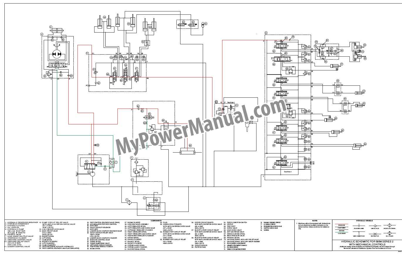
    The hydraulic system plays a crucial role in ensuring the smooth and effective performance of machinery. It is responsible for transmitting power through fluid dynamics, which allows various components to work together seamlessly. Proper understanding of how this system operates is key to optimizing overall machine efficiency, as well as minimizing wear and potential breakdowns.

    For enhanced performance, regular monitoring and maintenance of the hydraulic system are essential. Keeping the fluid clean and ensuring that all parts are functioning as intended will not only extend the system’s lifespan but also prevent costly repairs. By staying proactive, operators can ensure that their machinery continues to function at peak efficiency.

    Transmission and Drive Mechanism Breakdown

    The transmission and drive mechanism is crucial for ensuring smooth power delivery from the engine to the wheels. Understanding its components and how they work together helps in identifying potential issues and optimizing performance. This section provides an overview of the key elements involved in this process.

    • Gearbox: Responsible for adjusting the engine’s output to the appropriate speed and torque for the wheels, ensuring efficient power distribution.
    • Clutch System: Engages and disengages the transmission, allowing for smooth gear changes and preventing engine overload.
    • Drive Shafts: Transmit power from the gearbox to the wheels, maintaining rotational motion while compensating for any movement or angle changes.
    • Differential: Balances power between the wheels, enabling better control and handling, particularly during turns or uneven terrain.

    By understanding the basic function of these components, maintenance and troubleshooting become easier, helping to extend the longevity of the equipment and improve overall performance.

    Detailed View of the Steering Assembly

    The steering mechanism plays a crucial role in guiding the vehicle and ensuring smooth handling, making it an essential component of the system. Understanding how the various elements within the assembly work together provides insight into maintaining control and responsiveness during operation. This section highlights the key parts that form the steering system and their functions in achieving optimal steering performance.

    • Steering Wheel Linkage: This component connects the driver’s input to the rest of the assembly, transmitting motion to the steering components.
    • Hydraulic Cylinder: Responsible for converting fluid power into mechanical force, this part assists with turning the wheels smoothly and efficiently.
    • Pitman Arm: Transfers the rotational movement from the steering shaft to the drag link, guiding the wheels to move in the desired direction.
    • Drag Link: The link between the pitman arm and the tie rods, helping to transmit the motion further along the assembly.
    • Tie Rods: These elements connect the drag link to the wheel hubs, ensuring proper alignment and coordination of the wheels during steering.

    Each component is designed to work in harmony, ensuring the vehicle can respond precisely to the driver’s inputs, delivering both stability and ease of control, even

    Understanding the Electrical System and Wiring

    case 580 super m parts diagram

    The electrical system of machinery plays a crucial role in its overall functionality. This intricate network is responsible for powering various components and ensuring smooth operation. Understanding this system involves exploring the wiring, connections, and the components that contribute to effective electrical performance.

    Key Components of the Electrical System

    • Batteries: Provide the necessary power to start the engine and operate electrical systems.
    • Alternator: Charges the battery and supplies power to electrical components when the engine is running.
    • Fuses: Protect the electrical circuits by preventing overloads that can cause damage.
    • Relays: Act as switches that control the flow of electricity to various systems based on input signals.

    Wiring Configuration and Maintenance

    case 580 super m parts diagram

    Proper wiring configuration is essential for optimal performance. Regular maintenance helps prevent electrical failures and ensures safety. Consider the following tips:

    1. Inspect wiring regularly for signs of wear or damage.
    2. Ensure connections are secure and free from corrosion.
    3. Replace any damaged components promptly to maintain system integrity.

    Brake System Components and Their Functions

    case 580 super m parts diagram

    The brake system of heavy machinery is crucial for ensuring safety and effective operation. It comprises various elements that work together to bring the vehicle to a halt or slow its movement, providing control and stability during operation. Understanding these components and their specific roles is essential for maintenance and troubleshooting.

Component Description
Engine A robust power unit that drives the machine, ensuring smooth operation across diverse conditions.
Hydraulic System Enables the movement of attachments and implements, providing flexibility and control during tasks.
Transmission Facilitates the transfer of power from the engine to the wheels, offering stability and traction.
Axles and Tires These elements support mobility and ground contact, critical for handling rugged terrains.
Component Function
Brake Pedal Acts as the primary control for activating the brake system.
Brake Master Cylinder Converts pedal pressure into hydraulic force to operate the brakes.
Brake Lines Transmits hydraulic fluid from the master cylinder to the brake components.
Brake Calipers Holds the brake pads and applies pressure to them against the rotor.
Brake Pads Friction material that presses against the rotor to slow or stop the vehicle.
Brake Rotors Disc that the brake pads clamp onto to create friction and stop the wheels.
Parking Brake Mechanical system that keeps the vehicle stationary when parked.

Front and Rear Axle Diagrams Explained
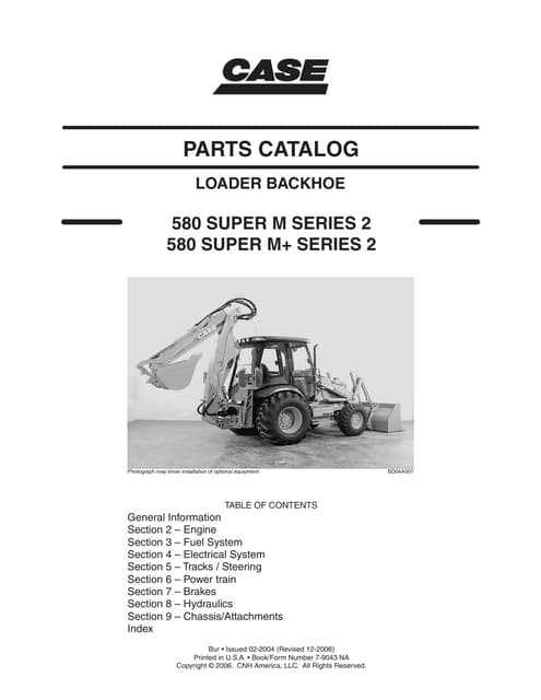
case 580 super m parts diagram

The understanding of front and rear axle layouts is essential for comprehending the overall functionality of heavy machinery. These components play a critical role in the vehicle’s mobility and stability, influencing how the machine interacts with various terrains. The following sections provide insights into the configurations and significance of these axles.

Understanding Axle Configurations
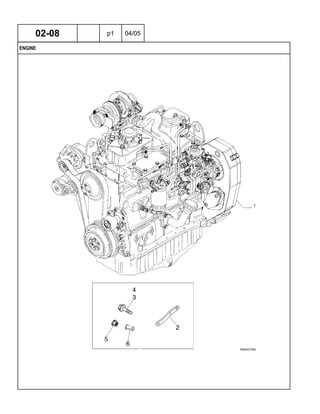
case 580 super m parts diagram

Axles are crucial elements that connect the wheels and allow for effective load distribution and movement. Their configurations can vary significantly, affecting performance and maneuverability. Here are some common types:

  • Live Axles: These are responsible for transmitting power to the wheels while supporting the vehicle’s weight.
  • Dead Axles: Unlike live axles, these do not transmit power but help in supporting the structure.
  • Steering Axles: These facilitate directional control, especially in complex terrains.

The Importance of Axle Layouts

Proper axle layouts enhance the machine’s performance, ensuring better traction and stability. A well-designed axle system contributes to:

  1. Improved Load Distribution: This prevents undue stress on any single component.
  2. Enhanced Maneuverability: Efficient axle designs allow for better handling and turning capabilities.
  3. Increased Durability: Quality materials and designs extend the lifespan of the vehicle.

In conclusion, a thorough understanding of front and rear axle structures is vital for effective maintenance and operation, ensuring optimal performance in various applications.

Maintenance Tips Using the Parts Diagram

Regular upkeep of heavy machinery is essential for ensuring longevity and optimal performance. Understanding the various components and their functions can significantly enhance maintenance practices. By utilizing an illustrated guide of the equipment’s assembly, operators can effectively identify and address potential issues before they escalate.

Here are some useful suggestions for maintaining your machinery effectively:

  • Conduct routine inspections to identify any wear and tear on components.
  • Keep a log of maintenance activities to track the condition of each part over time.
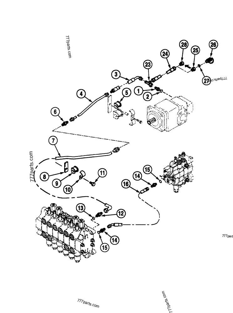
  • Utilize a detailed schematic to locate specific components when performing repairs or replacements.
  • Ensure all components are correctly lubricated to prevent friction and overheating.
  • Follow the manufacturer’s recommendations for maintenance intervals and procedures.

By implementing these practices and regularly consulting the illustrated guide, operators can maintain the machinery in peak condition, enhancing both safety and efficiency.