Understanding the structure and functionality of key elements in modern farming equipment is essential for maintaining its efficiency and longevity. With a well-organized breakdown of the various mechanical elements, users can easily identify and address maintenance needs, ensuring that the machine continues to operate smoothly under varying conditions.
In this section, we delve into the intricate layout of vital components, offering a clear visualization of how each section is interconnected. This exploration not only simplifies repair processes but also provides valuable insights into the overall design of the machinery. Such knowledge empowers users to make informed decisions when it comes to replacements and repairs.
Through a detailed examination, we offer a deeper understanding of how various sections function together, enhancing both operational reliability and long-term performance. This structured guide serves as a useful tool for anyone looking to maintain or restore the mechanical integrity of their equipment.
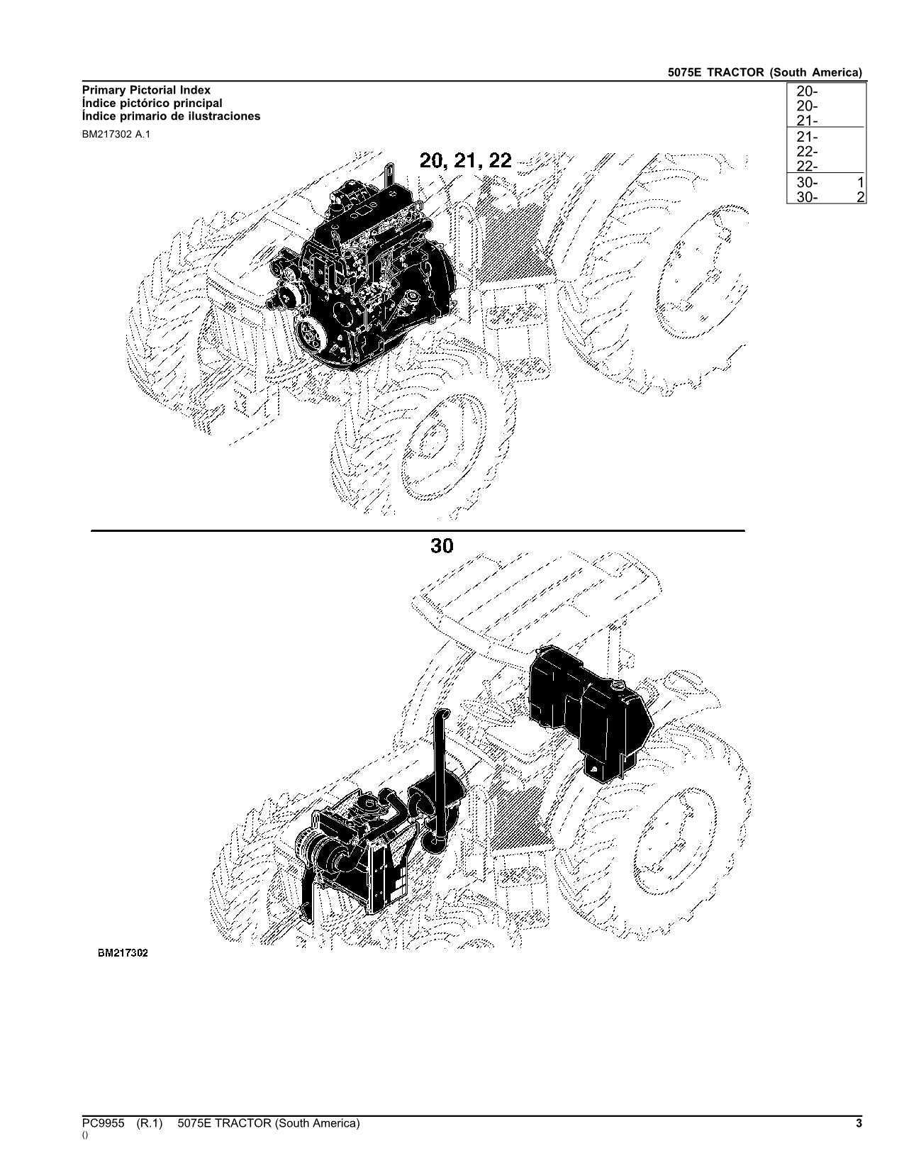
Comprehensive Overview of the John Deere 5075E Model
This model is designed to meet the diverse needs of modern agricultural operations, providing reliable performance and versatility in various tasks. It is known for its sturdy construction and adaptability to different environments, making it a dependable choice for both small-scale and large-scale farms.
- Engine and Performance: The machine is powered by a robust engine that ensures consistent efficiency, even during demanding tasks. Its design focuses on fuel economy and long-term durability.
- Transmission Options: Different transmission configurations allow operators to choose the setup best suited for their specific field requirements, optimizing both ease of use and productivity.
- Hydraulic System: The hydraulic system is designed for seamless integration with a variety of attachments, enhancing the overall functionality and efficiency of the equipment during fieldwork.
- Comfort and Usability: The operator cabin is designed with ergonomic features that ensure comfort during extended work periods. Visibility, control layout, and accessibility are optimized for a superior user ex
Key Components Breakdown
In this section, we explore the essential elements that make up the core functionality of the equipment. By understanding how various units are structured and how they work together, it becomes easier to maintain optimal performance and quickly address any potential issues.
Engine and Transmission Systems

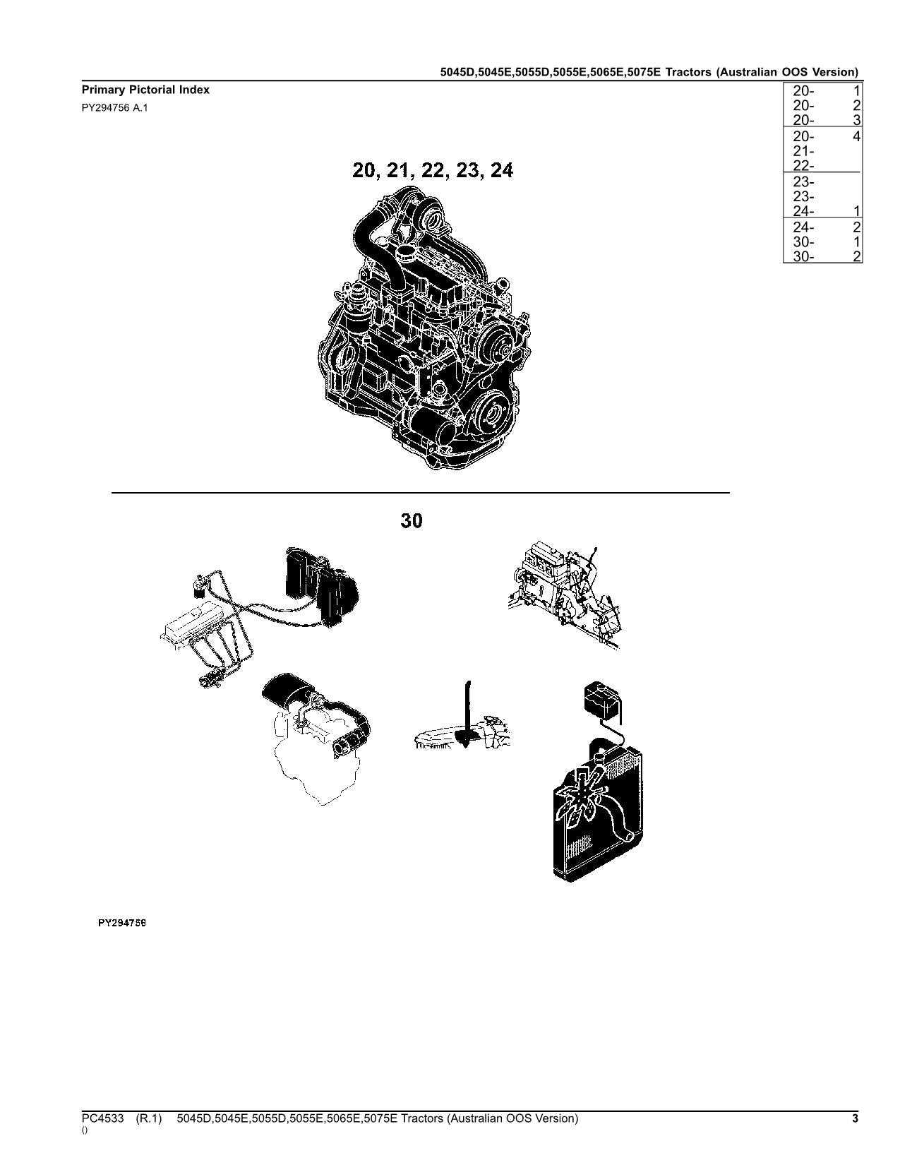
The heart of the machine, responsible for converting energy into mechanical power, includes several interconnected elements. These systems ensure smooth operation and provide the necessary force for various tasks. Key features include the fuel delivery mechanism, cooling system, and transmission that coordinates power distribution.
Hydraulics and Electrical Systems

These networks are vital for controlling the machine’s movement and auxiliary functions. The hydraulic system, equipped with multiple valves and pumps, manages the lifting and lowering of attachments. Simultaneously, the electrical framework ensures that sensors, lights, and control units communicate effectively.
Component Function Engine Provides mechanical energy for operation Detailed Analysis of Engine Parts
Understanding the inner workings of a machinery’s engine is crucial for efficient maintenance and optimal performance. This section offers an in-depth examination of the key components, their roles, and how they interact to ensure smooth operation.
Main Engine Components
- Cylinder Block: The core structure that houses several integral systems, including the cylinders, which are vital for combustion.
- Piston: This movable element generates mechanical power by transforming energy from combustion into motion.
- Crankshaft: Converts the linear motion of the pistons into rotational motion to drive the machinery.
Auxiliary Systems
- Cooling System: Ensures temperature regulation by dissipating heat, preventing overheating and maintaining operational efficiency.
- Lubrication System: Distributes oil
Hydraulic System Layout Explained

The fluid-driven mechanism plays a critical role in ensuring smooth and efficient operation across various functions of the equipment. Understanding the configuration of this system helps in identifying how energy is transferred, controlled, and utilized through interconnected components.
At the core of the system lies a network of tubes, pumps, and valves that manage the flow of pressurized liquid. This setup is designed to power several essential functions, ranging from lifting to precise control of movements. The entire system relies on a well-orchestrated balance between pressure and flow to achieve maximum performance.
Key elements of this system include fluid reservoirs, control valves, and actuators, each playing a vital role in transforming mechanical power into fluid energy and vice versa. The layout ensures efficient fluid circulation and precise control over the system’s functions, which is crucial for maintaining operational stability.
Transmission Components and Their Functions
The transmission system plays a critical role in transferring power from the engine to the wheels, ensuring smooth operation and efficient performance in a wide variety of conditions. Its various elements work together to manage speed, direction, and torque, providing the necessary control over the vehicle’s movement.
Component Function Clutch Engages and disengages the connection between the motor and the drivetrain, allowing for smooth shifting of gears. Gearbox Contains a set of gears that adjust the output speed and torque, depending on the conditions and operator’s needs. Shift Lever Allows the operator to select different gears, enabling changes in speed and torque. Transmission Shafts Transfer power between various parts of the transmission, Steering Mechanism and Its Role
The steering mechanism is a vital component in any agricultural vehicle, enabling precise navigation and control. It ensures that the operator can maneuver effectively across diverse terrains, enhancing productivity and efficiency in various tasks. Understanding the intricacies of this system is essential for optimal vehicle performance and safety during operation.
Functionality and Components
This system comprises several key elements that work in harmony to facilitate smooth steering actions. The primary components include the steering wheel, linkage systems, and the steering gear. Each part plays a critical role in translating the operator’s inputs into effective steering responses, allowing for agile movements and accurate positioning.
Maintenance Considerations
Regular maintenance of the steering assembly is crucial to ensure reliable functionality. Operators should routinely check for wear and tear, lubrication levels, and proper alignment of components. Addressing any issues promptly can prevent more significant problems, ensuring the longevity of the steering system and overall vehicle performance.
Electrical System and Wiring Layout
The electrical framework of agricultural machinery plays a crucial role in ensuring efficient operation and reliable performance. This section provides a comprehensive overview of the configuration and interconnections that facilitate the functionality of the equipment. Understanding the layout is essential for maintenance and troubleshooting, as it helps users identify components and their relationships within the system.
A well-organized wiring configuration enhances the overall functionality of the machine, supporting various electrical components such as the ignition system, lighting, and instrumentation. Each part is strategically positioned to optimize accessibility and prevent interference, ensuring seamless integration with other systems. Proper documentation of the wiring layout not only aids in repairs but also assists in modifications and upgrades.
Familiarity with the electrical network allows operators to address potential issues proactively. Regular inspections of connections and components can prevent malfunctions and enhance longevity. Comprehensive knowledge of the system also empowers users to make informed decisions when seeking replacements or enhancements.
Maintenance Guidelines for Common Parts
Regular upkeep of essential components is crucial for ensuring optimal performance and longevity of machinery. Adopting systematic maintenance practices can prevent premature wear and potential failures. Understanding the specific needs of frequently used elements allows for efficient service and reduces downtime.
Inspection: Conduct routine checks to identify any signs of wear, leaks, or damage. Regularly examining these components helps catch issues early, allowing for timely intervention.
Cleaning: Keep all parts clean from debris and contaminants. Accumulation of dirt can lead to malfunctions and decreased efficiency. Use appropriate cleaning agents and methods to maintain the integrity of each element.
Lubrication: Ensure that moving parts are adequately lubricated to reduce friction and prevent overheating. Follow manufacturer recommendations regarding the type and frequency of lubrication to optimize performance.
Replacement: Be proactive in replacing worn or damaged components. Keeping a stock of commonly used replacements can facilitate swift repairs and minimize operational disruptions.
Documentation: Maintain records of all maintenance activities. Documenting inspections, cleanings, and replacements provides insight into the operational history and aids in planning future upkeep.
Understanding Fuel System Diagram
The fuel delivery framework in agricultural machinery plays a crucial role in ensuring optimal performance and efficiency. This intricate system consists of various components that work in unison to manage the flow and filtration of fuel. A comprehensive overview of this framework is essential for effective maintenance and troubleshooting.
Key Components: Within the fuel delivery framework, each element serves a distinct function, from the fuel tank that stores the liquid to the fuel injectors that precisely dispense it into the engine. Understanding these components aids in recognizing their interconnections and how they influence overall functionality.
Operational Principles: The mechanics of fuel distribution involve several stages, including filtration, transfer, and injection. By grasping the operational principles behind these stages, operators can better appreciate how fuel quality and delivery affect the machinery’s performance and longevity.
Maintenance Importance: Regular inspection and maintenance of the fuel delivery system are vital. Ensuring that all components are functioning correctly helps prevent breakdowns and promotes the longevity of the equipment. Being familiar with the intricacies of this system empowers users to take proactive measures for upkeep.