Drive Shaft: Connects the power source
Diagram of the Mower Cutting System
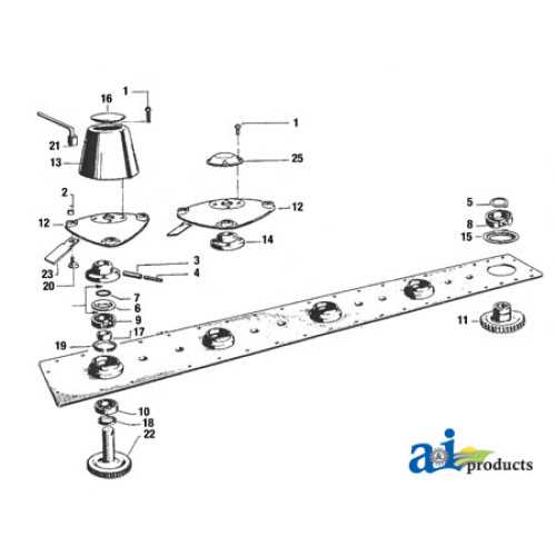
The structure of the mower’s cutting mechanism is essential for efficient grass trimming and overall system performance. Understanding the core components and their arrangement will help ensure smooth operation and quick troubleshooting in case of issues.
Main Components of the Cutting Mechanism
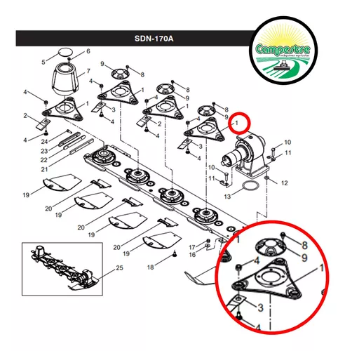
- Blades: These are responsible for cutting the grass, rotating at high speed to achieve clean cuts. Sharpness and balance are crucial for optimal performance.
- Blade Mounting: The blades are attached securely to a spindle or similar component, ensuring stable rotation during operation.
- Spindle Assembly: This part provides the axis for blade rotation and is connected to the mower’s drive system.
Drive and Support Elements
Understanding the Gearbox and Drive Mechanism
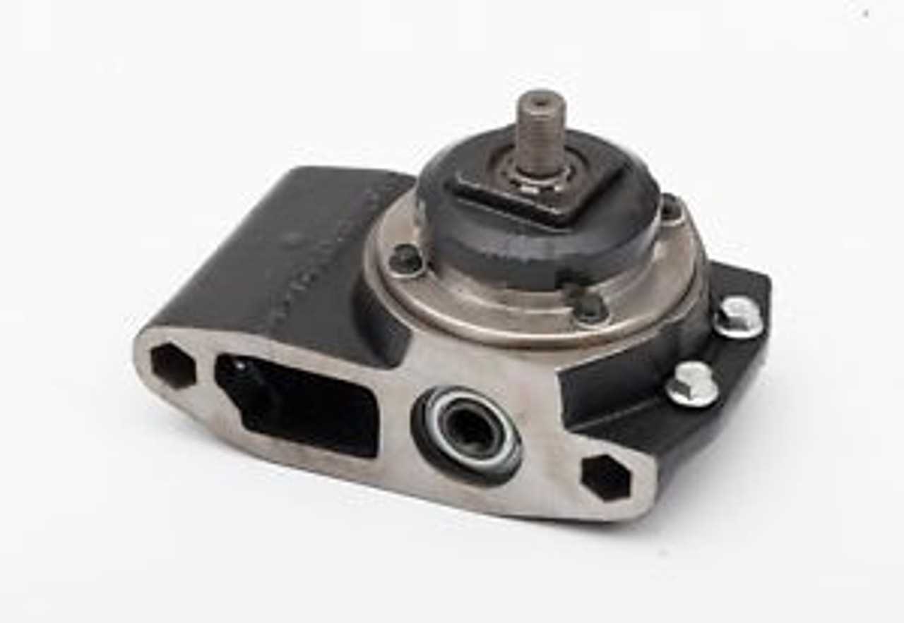
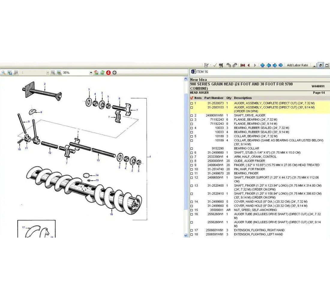
The gearbox and drive mechanism play a crucial role in ensuring the smooth operation of agricultural machinery. These components are responsible for transferring power efficiently from the engine to the working parts, enabling optimal performance during field operations. By understanding how these systems interact, one can better maintain and troubleshoot mechanical issues, ensuring longevity and reliability.
Key Components of the Gearbox
- Input Shaft: Receives power from the engine and transmits it into the gearbox for further distribution.
- Gears: Different sets of gears are responsible for adjusting speed and torque to meet various operational needs.
- Output Shaft: Delivers the adjusted power to the drive mechanism, facilitating movement or specific machine functions.
How the Drive Mechanism Works
The drive mechanism converts the power transmitted by the gearbox into
Blade Assembly and Its Functionality
The blade assembly is a crucial component designed for efficient operation in a variety of machinery. It consists of multiple parts that work in unison to ensure precise cutting, slicing, or shredding, depending on the machine’s purpose. Understanding its structure and role is essential for maintaining the machine’s performance and ensuring safety during operation.
Key Components of the Blade Mechanism
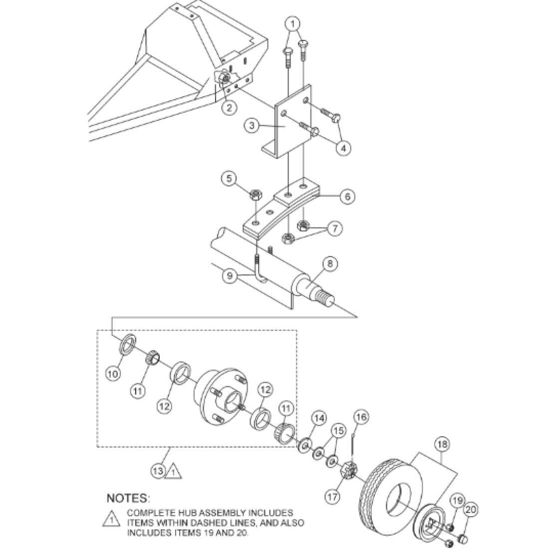
The primary elements of the blade assembly include the cutting edge, mounting hardware, and rotational mechanism. The cutting edge is specifically crafted to handle different materials, providing the necessary sharpness for clean cuts. The mounting hardware ensures the blade remains securely in place, while the rotation mechanism allows for smooth movement and control during use.
Functionality and Performance
Each part of the assembly works together to optimize the cutting process. The precise alignment of the blade and its movement contribute to the machine’s overall efficiency. Regular
Exploring the Hydraulic Lift System
The hydraulic lift system plays a critical role in facilitating movement and enhancing operational efficiency in machinery. By harnessing the power of pressurized fluids, it enables heavy components to be raised, lowered, and precisely controlled. This technology is essential for providing both the strength and accuracy needed in demanding environments.
Key Components of the Hydraulic System
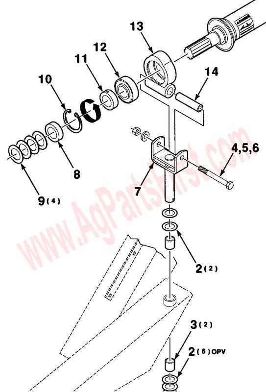
- Pump: Responsible for circulating hydraulic fluid through the system to generate pressure.
- Hydraulic Cylinder: The actuator that transforms hydraulic energy into mechanical movement.
- Valves: Direct the flow of fluid to control speed and direction of the lift system.
- Reservoir: Holds the hydraulic fluid, ensuring an uninterrupted supply during operation.
Functionality and Operation
When the system is activated, the hydraulic pump draws fluid from the reservoir and pushes it into the cylinder under high pressure. The fluid’s force moves a piston inside the cylinder, which in turn raises or lowers the attached load. By adjusting the flow of the fluid through the valves, operators can precisely control the speed and movement of the lift, ensuring smooth and accurate operation in various tasks.
Detailed View of the PTO Shaft
The PTO shaft is a crucial component in machinery that transfers mechanical power from the engine to external devices. Its precise function ensures smooth operation and effective performance across various applications, such as agricultural equipment and industrial machinery. Understanding the specific elements of the shaft is essential for proper maintenance and optimal usage.
| Component |
Description |
| Universal Joint |
Facilitates the transfer of torque between the rotating shaft and other mechanical parts, allowing for flexibility in movement. |
| Slip Clutch |
Prevents damage to the system by disengaging under excessive torque, ensuring the safety of the machinery. |
| Shield |
Protects the PTO shaft from debris, dust, and physical damage, while also reducing the risk of accidental contact with moving parts. |
| Safety Guard |
Enhances operator safety by covering the rotating parts of the PTO shaft, preventing injury during operation. |
| Coupling |
Connects the PTO shaft to the machine or implement, ensuring secure and reliable power transmission. |
Maintenance Tips for Key Parts
Proper upkeep of essential components is crucial to ensuring optimal performance and longevity of any machine. Regular attention to these elements can help prevent premature wear, reduce downtime, and improve overall efficiency. Understanding how to care for these key elements ensures that they remain functional and reliable throughout their service life.
1. Regular Cleaning: Keeping all moving parts clean is essential. Dust, dirt, and debris can lead to friction and wear, so it’s important to routinely inspect and clean these areas. Use appropriate cleaning solutions and avoid harsh chemicals that could damage sensitive surfaces.
2. Lubrication: Proper lubrication minimizes friction between components, reducing wear and tear. Always use the manufacturer’s recommended lubricant, and apply it sparingly to avoid excess buildup, which could attract dirt.
3. Periodic Inspections: Regularly inspect critical components for signs of damage, misalignment, or unusual wear. Early detection of any issues allows for timely repairs, preventing more severe damage down the line.
4. Tightening Connections: Over time, bolts and screws may loosen, leading to instability. Periodically check all fasteners to ensure they are securely tightened to prevent vibrations that could cause further damage.
5. Replacing Worn Components: If certain elements show significant wear, it’s essential to replace them promptly. Delaying the replacement of worn-out parts can result in additional stress on other components, leading to more complex issues.
By following these simple but effective maintenance practices, you can significantly extend the lifespan of your equipment and keep it functioning optimally for years to come.
Troubleshooting Common Issues in the 5209

When operating machinery, it is not uncommon to encounter problems that can affect efficiency and performance. Identifying and addressing these issues quickly ensures minimal downtime and optimal functionality. Below are common challenges users may face and helpful approaches to resolving them effectively.
| Issue |
Possible Cause |
Solution |
| Unresponsive controls |
Electrical connection failure or malfunctioning components |
Check all wiring and connections for loose or damaged parts. Test individual components for proper function. |
| Irregular movement |
Worn-out or misaligned mechanical parts |
Inspect moving parts for signs of wear or misalignment. Replace or adjust as necessary. |
| Overheating |
Improper ventilation or blocked cooling system |
Ensure vents and cooling systems are clean and free from debris. Check the fan and cooling components for damage or obstructions. |
| Excessive noise |
Loose components or insufficient lubrication |
Inspect for loose parts and tighten if necessary. Apply lubrication to moving parts if required. |
| Erratic performance |
Software or firmware malfunction |
Check for software updates or resets. Reinstall firmware if necessary to restore proper functioning. |
By systematically checking these common issues and applying the suggested solutions, you can keep your equipment running smoothly and efficiently, avoiding unnecessary delays and repairs.
