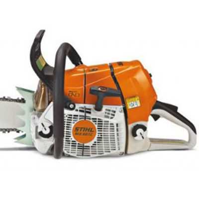
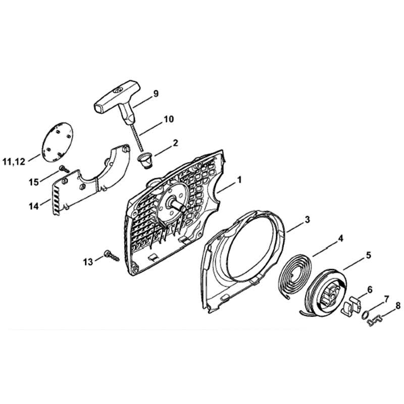
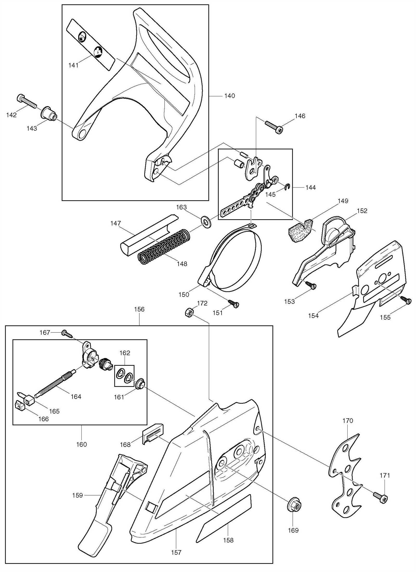
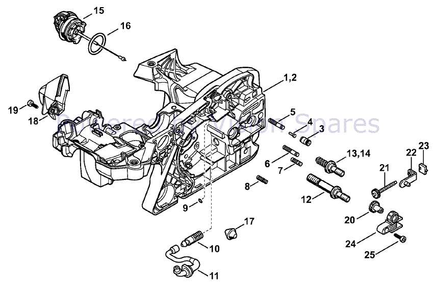
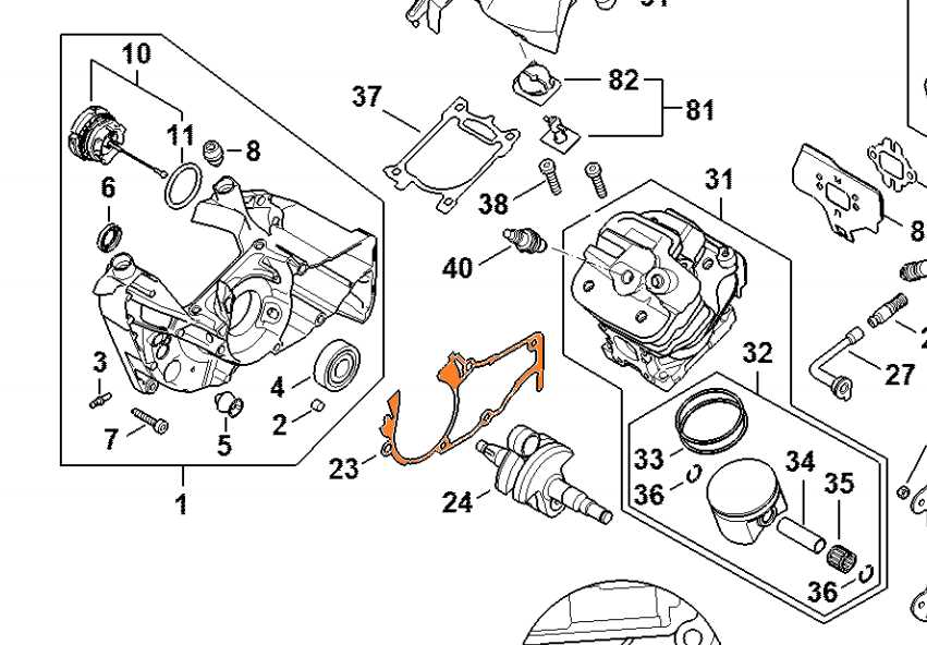
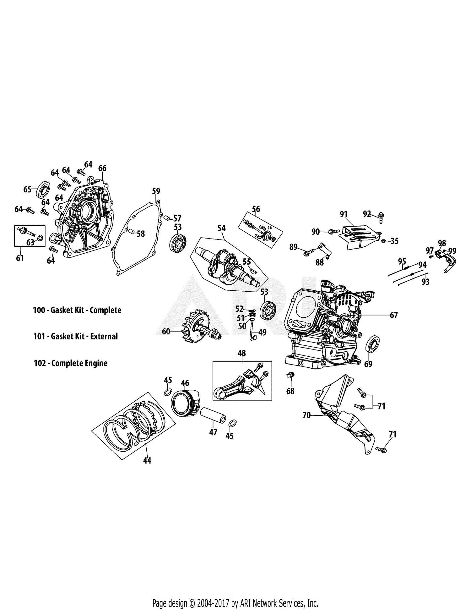
Clean the guide bar and sprocket area to avoid buildup of debris that can affect performance
Ignition System Structure and Elements
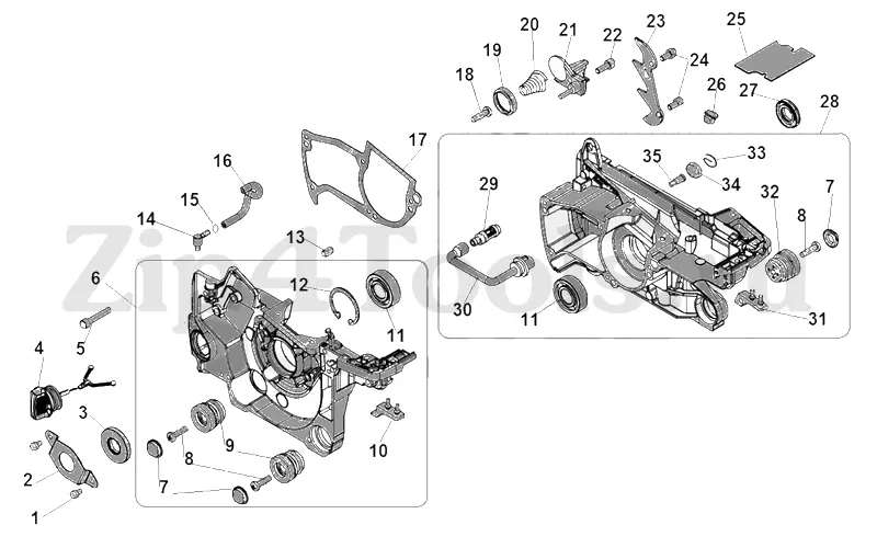
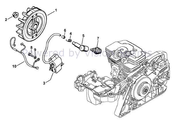
The ignition system plays a crucial role in ensuring the engine operates smoothly and efficiently. It is responsible for generating the necessary energy to ignite the air-fuel mixture, ultimately powering the machine. Understanding the components and how they work together can help in diagnosing issues and maintaining optimal performance.
- Spark Plug: This component delivers the electrical spark that ignites the fuel mixture, initiating combustion.
- Ignition Coil: The coil transforms the battery’s low voltage into the high voltage required to create a spark at the spark plug.
- Flywheel: A rotating part that helps generate the magnetic field needed for the ignition system to produce a spark.
- Magneto: This device generates electric current by using the flywheel’s motion, supplying power to the ignition system.
- Wiring: Connects various components of the system, ensuring smooth transmission of electrical signals.
These elements are interconnected and must function harmoniously to ensure reliable ignition and engine performance. Proper maintenance of these com
Air Filter and Exhaust System Explanation
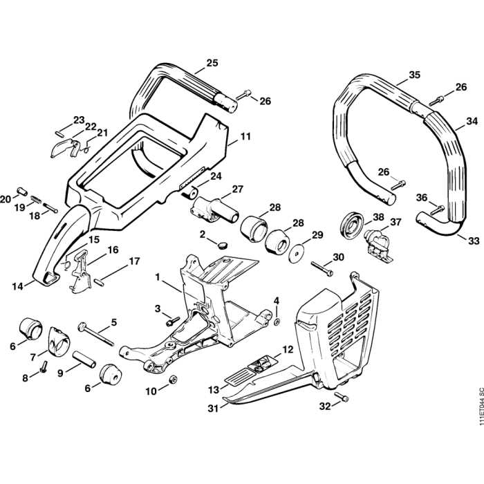
The air filtration and exhaust mechanisms are crucial components that contribute to the efficiency and performance of small engines. These systems work in tandem to ensure optimal air intake and effective expulsion of gases produced during combustion. A well-functioning air filter allows clean air to enter the engine, while a properly designed exhaust system helps in releasing burnt gases, thereby maintaining the engine’s health and reducing emissions.
Importance of the Air Filter
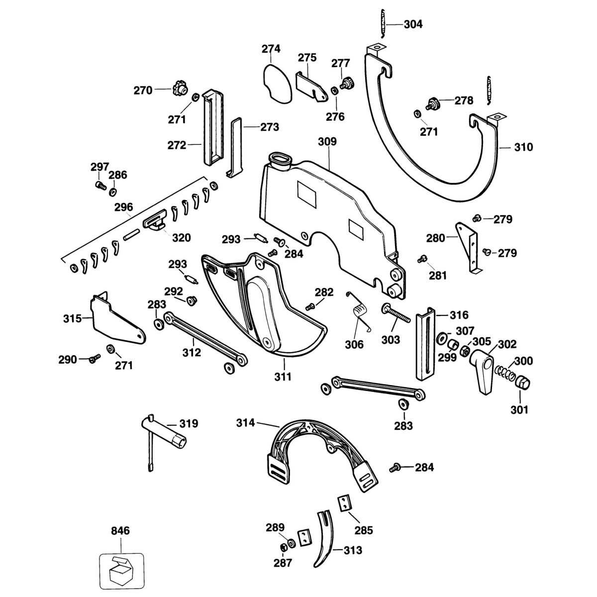
The air filter serves as the first line of defense against contaminants that can harm the engine. It is essential for maintaining air quality, which directly affects engine performance. Key functions of the air filter include:
- Preventing dust, dirt, and debris from entering the engine.
- Enhancing fuel efficiency by ensuring proper air-fuel mixture.
- Extending engine life by reducing wear and tear.
Exhaust System Functionality
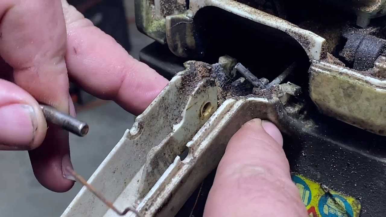
The exhaust system plays a vital role in the overall operation of the engine. Its primary responsibilities are:
- Directing burnt gases away from the engine.
- Minimizing noise produced during operation.
- Reducing harmful emissions through proper gas flow management.
In conclusion, the air filter and exhaust system are integral to the effective functioning of small engines, ensuring optimal performance while minimizing environmental impact.
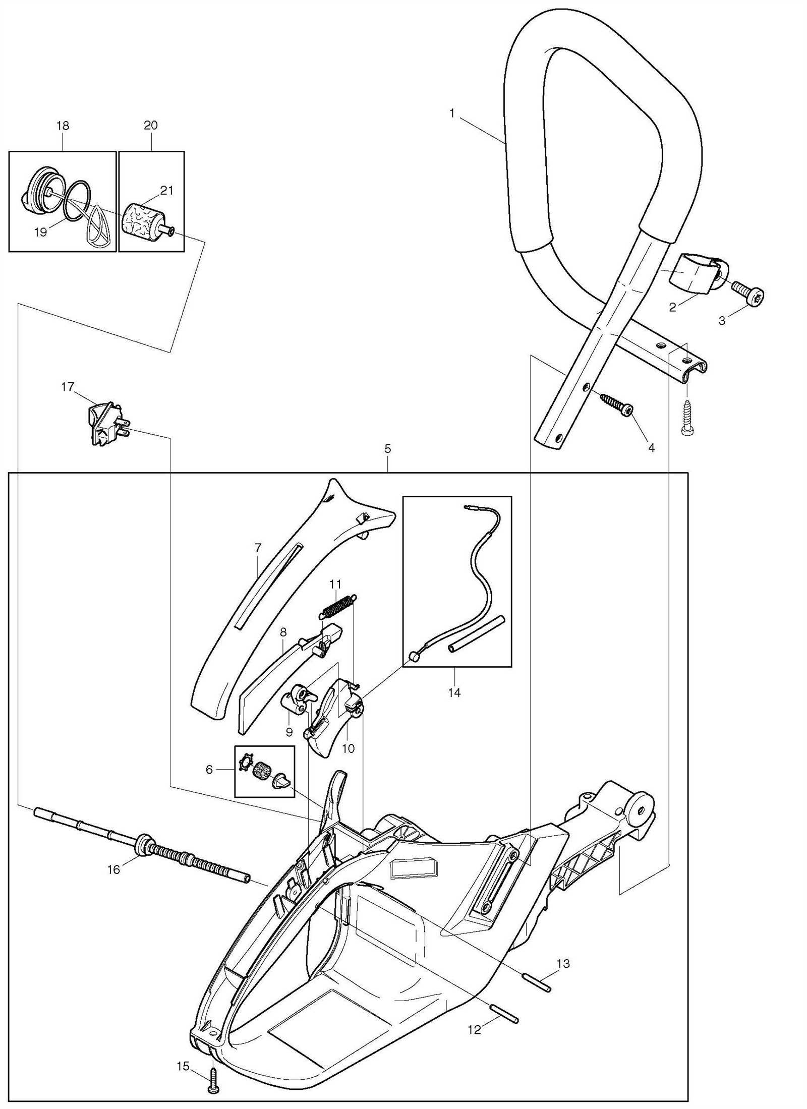
Handle and Control Layout Overview
The configuration of the grip and operational components is crucial for achieving optimal performance and user comfort. This section provides insights into the arrangement of controls that enhance functionality and accessibility. An intuitive layout allows for seamless interaction, promoting efficient handling during use.
At the core of the design are various controls, including throttle mechanisms and stop switches, strategically positioned for easy reach. The ergonomic placement minimizes strain, allowing users to maintain a natural grip while operating the equipment. This careful consideration of control layout ensures that users can focus on their tasks without unnecessary distractions.
Additionally, the structure of the handle offers stability and support, contributing to overall balance. A well-designed handle not only facilitates maneuverability but also enhances safety by providing a secure grip in various operating conditions. Understanding the intricacies of this layout can significantly improve the user experience and operational efficiency.
Clutch Assembly and Drive System Insights
The clutch mechanism plays a pivotal role in the efficiency and functionality of power equipment. This assembly is responsible for transferring torque from the engine to the drive system, ensuring smooth operation and optimal performance. Understanding the components involved in this system can provide valuable insights into maintenance and potential troubleshooting.
Key elements of the clutch assembly include the clutch drum, drive belt, and various springs that work in unison to facilitate engagement and disengagement. The drive system, on the other hand, is designed to transmit power effectively, making the entire operation seamless. Each part contributes to the overall performance, impacting not only the functionality but also the longevity of the equipment.
| Component |
Description |
Function |
| Clutch Drum |
A cylindrical component that houses the clutch pads. |
Engages and disengages the drive system from the engine. |
| Drive Belt |
A flexible band that transmits power from the engine to the drive system. |
Transfers torque, allowing the equipment to function. |
| Springs |
Mechanical components that assist in the engagement process. |
Help in controlling the clutch action, ensuring smooth transitions. |
| Clutch Pads |
Friction materials that create the necessary grip within the drum. |
Facilitate power transfer by gripping the drum during engagement. |
Regular inspection and maintenance of these components are crucial for ensuring optimal performance. Recognizing signs of wear or damage can prevent larger issues and enhance the longevity of the equipment. Keeping the drive system in good working condition not only improves efficiency but also provides a safer operating experience.
Troubleshooting Common Stihl 311y Issues
When working with outdoor power equipment, encountering operational challenges is not uncommon. Understanding the typical problems that may arise, along with their potential solutions, can significantly enhance your experience and efficiency.
Difficulty Starting: If the equipment fails to start, check the fuel supply. Ensure that fresh, clean fuel is used, and examine the ignition system for any faults. Cleaning the spark plug may also improve performance.
Engine Stalling: An engine that stalls frequently could indicate a clogged air filter or fuel line. Inspect these components and clean or replace them as necessary to restore proper airflow and fuel delivery.
Overheating: Overheating can occur due to insufficient lubrication or debris obstructing airflow. Regular maintenance, such as checking oil levels and cleaning the cooling fins, is essential to prevent this issue.
Unusual Noises: Any strange sounds during operation may signal a mechanical issue. It is advisable to stop using the equipment immediately and inspect for loose parts or damaged components that require attention.
Poor Cutting Performance: If cutting efficiency declines, inspect the cutting blade for dullness or damage. Sharpening or replacing the blade can improve performance, ensuring that tasks are completed effectively.
