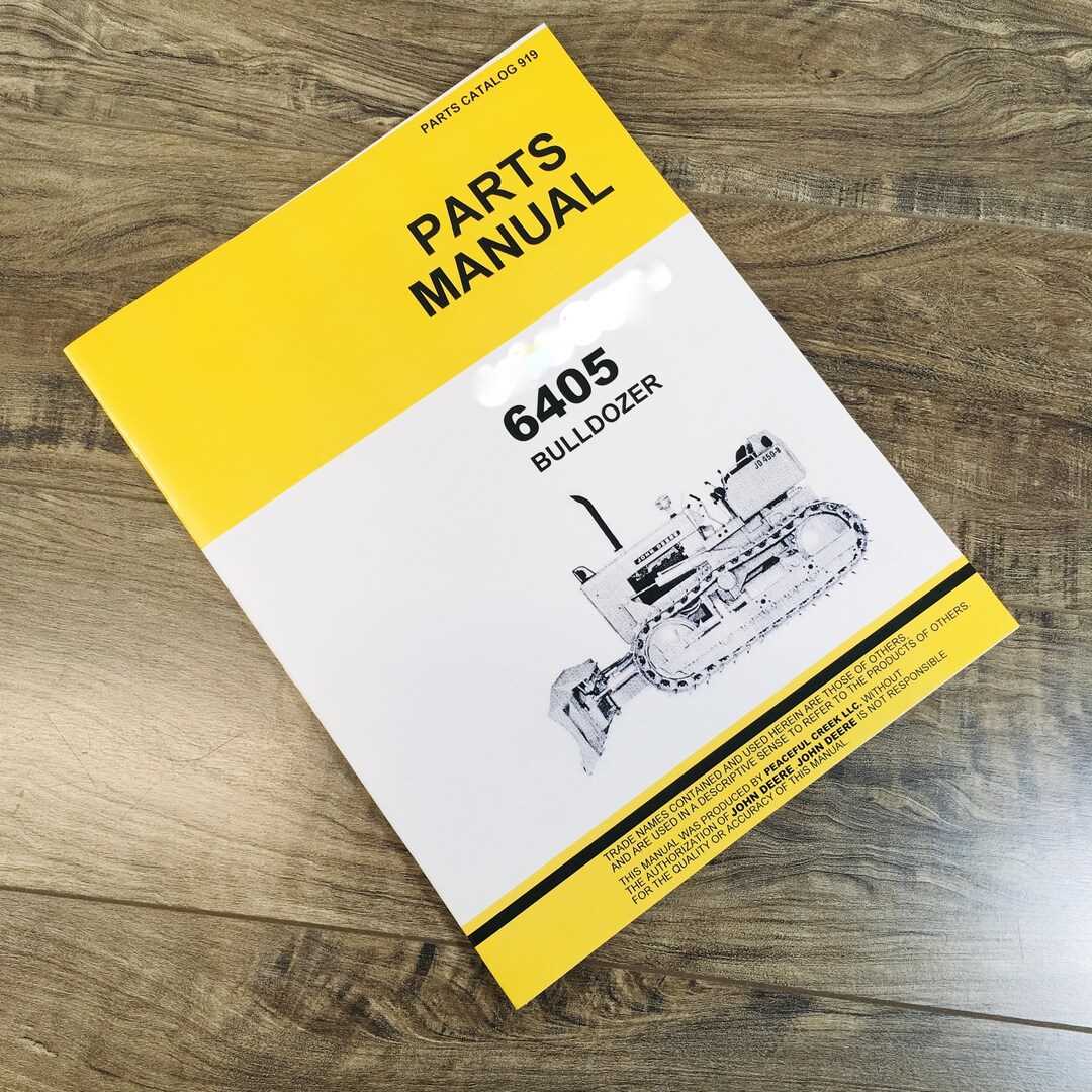
Maintaining machinery in top condition is critical for efficient farming operations. To ensure your equipment functions reliably, it’s important to be familiar with its various components and how they work together. Understanding the layout and connections between essential elements can help you perform timely maintenance and avoid potential downtimes.
In this guide, we will explore the organization and arrangement of key elements in some widely used farming equipment. By gaining insight into how these parts are structured, you will be better equipped to handle repairs, replacements, and regular upkeep. This knowledge can make a significant difference in ensuring the long-term durability of your tools.
Knowing where each component fits and how it interacts with others is invaluable, whether you are a seasoned professional or new to the field. By understanding these relationships, you’ll be able to troubleshoot issues with greater confidence and accuracy.
Overview of John Deere 450 Components
The machinery in question is designed with a variety of essential elements that contribute to its functionality and efficiency. This robust equipment consists of various interconnected systems, each playing a crucial role in ensuring smooth operation and durability. Understanding how these systems work together helps in maintaining optimal performance and handling tasks effectively.
From the core mechanical sections responsible for movement to the hydraulic and control mechanisms, every element has been engineered for reliability in demanding conditions. These components are built for longevity, ensuring that the equipment can endure heavy workloads and diverse applications in different environments.
Additionally, maintaining these systems is essential for continued productivity. By regularly inspecting and servicing key parts, operators can extend the lifespan of the machine and prevent costly repairs. With a focus on both strength and precision, this equipment remains a trusted choice for various industrial and agricultural tasks.
Main Systems and Key Assemblies
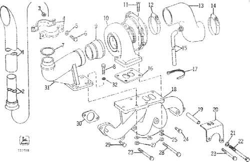
This section outlines the primary components and assemblies crucial for the efficient functioning of machinery. Understanding these interconnected systems is essential for ensuring proper operation, maintenance, and troubleshooting when necessary.
- Engine Unit: The heart of the machine, responsible for generating the power needed to drive all mechanical operations.
- Transmission System: Transfers power from the engine to the wheels or tracks, enabling movement and control over different terrains.
- Hydraulic Assembly: Controls various functions such as lifting, tilting, or rotating different attachments, ensuring precision in performance.
- Cooling Mechanism: Maintains optimal engine temperature by dissipating heat and preventing overheating during extended use.
- Fuel Delivery System: Ensures a steady flow of fuel from the tank to the engine, regulating performance and efficiency.
- Electrical Circuitry: Powers critical components such as the ignition system, lights, and sensors, while managing electronic inputs and outputs.
Each of these assemblies plays a vital role in the overall
Detailed Breakdown of Hydraulic Parts
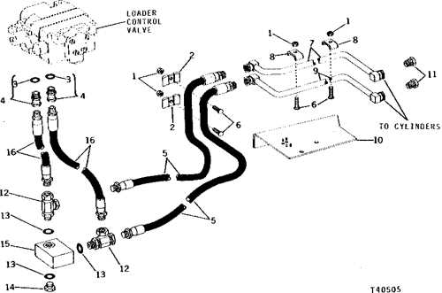
The hydraulic system plays a critical role in the efficient operation of various mechanical components, ensuring the smooth performance of lifting, lowering, and fluid distribution tasks. This section provides a comprehensive overview of the primary elements that contribute to the functioning of the hydraulic mechanism, explaining their roles and how they interact to maintain the overall system integrity.
Main Hydraulic Components
The central components of the hydraulic setup include pumps, valves, cylinders, and hoses. The pump is responsible for generating the necessary fluid pressure, while the valves regulate flow and direction. Cylinders convert hydraulic energy into mechanical force, enabling the machine’s movement, and hoses serve as conduits for fluid transmission between these elements.
Key Functional Relationships
Each part of the hydraulic system is intricately connected. The pump ensures that pressurized fluid reaches the valves, which then direct the flow to the appropriate cylinders. The cylinders act as the system’s muscles, performing the actual physical tasks, whether it’s raising a load or moving components. Without proper synchronization of these parts, the overall performance would be compromised.
Engine Components and Their Functions
An internal combustion engine consists of multiple critical elements working together to convert fuel into mechanical energy. These elements, each with a unique role, ensure smooth operation, power delivery, and efficiency. Understanding how these components function provides insight into the overall mechanism and helps maintain optimal performance.
Main Structural Elements
The core structural elements include the cylinder block, which houses the cylinders where combustion takes place, and the crankshaft, responsible for converting the linear movement of the pistons into rotational motion. The cylinder head is mounted atop the block, sealing the combustion chambers and housing intake and exhaust valves.
Supporting Mechanisms
Supporting mechanisms such as the camshaft and timing belt synchronize the opening and closing of valves with piston movement. The fuel injection system ensures a precise mix of fuel and air is delivered for combustion, while the cooling system prevents overheating, maintaining the engine’s temperature within optimal limits.
Transmission and Drive Mechanism Overview
The transmission and drive mechanism form the core of the vehicle’s ability to convert engine power into motion. This system ensures efficient power delivery to the wheels, allowing smooth operation under various conditions. The design of the drive components aims to maintain stability, enhance durability, and optimize performance across different terrains.
Main Components
- Gearbox: Responsible for adjusting the engine’s power to different speeds and torque levels. It allows the machine to perform effectively at various speeds.
- Drive Axles: These shafts transmit the torque from the transmission to the wheels, ensuring proper rotation and force distribution.
- Differential: A critical part that distributes power between the wheels, especially useful when turning, as it allows each wheel to rotate at different speeds.
Power Transfer Process
The power generated by the engine is routed through the transmission, where it is modulated based on speed and torque requirements. The system’s efficiency depends on the synchronization of the transmission with other drive components, ensuring smooth transitions between different gears and operational states.
- Engine Power Output: Energy from
Electrical System and Wiring Diagram Insights
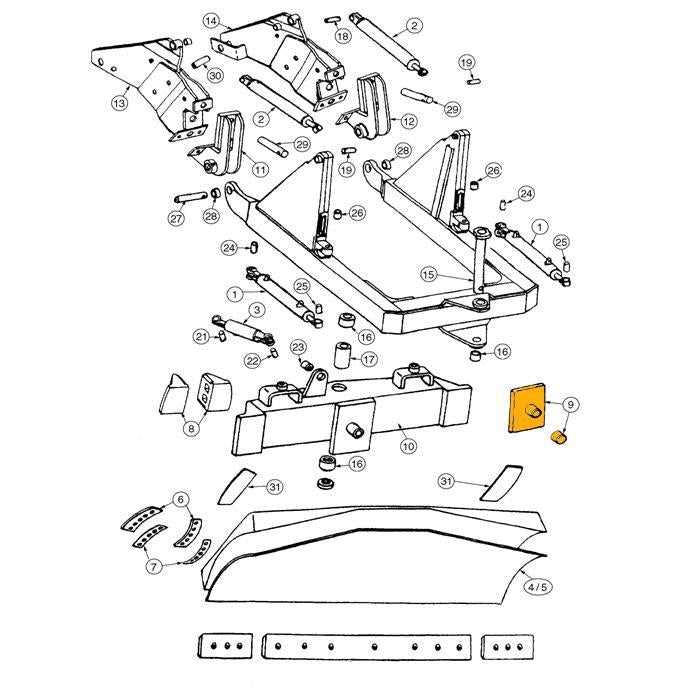
The electrical configuration of machinery plays a crucial role in its overall performance and functionality. Understanding the intricacies of these systems, along with their layout, can significantly aid in troubleshooting and maintenance efforts. This section delves into the components involved in the electrical setup, emphasizing the importance of a well-organized wiring structure.
Key Components of the Electrical Setup
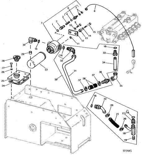
At the heart of any effective electrical system are various essential elements, including the battery, starter, alternator, and fuses. Each component serves a specific purpose, ensuring that energy is efficiently distributed throughout the equipment. Familiarizing oneself with these parts allows for quicker identification of potential issues, thereby streamlining repair processes.
Understanding Wiring Structures
A clear and systematic wiring layout is paramount for optimal functioning. It not only facilitates the flow of electricity but also minimizes the risk of short circuits and electrical failures. Visual representation of the wiring layout can aid operators and technicians in comprehending how different parts are interconnected. This knowledge is vital for executing repairs and implementing upgrades safely and effectively.
In summary, a comprehensive understanding of the electrical framework and its wiring organization is indispensable for ensuring reliable operation and longevity of equipment. Engaging with these insights empowers users to maintain their machinery with confidence and competence.
Track Assembly and Suspension Parts
The track assembly and suspension components play a crucial role in the performance and stability of heavy machinery. These elements work together to ensure proper traction and support, allowing for efficient operation in various terrains. Understanding the arrangement and functionality of these parts is essential for maintenance and troubleshooting, ensuring optimal performance during use.
Components of Track Assembly
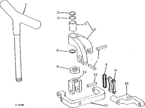
The track assembly consists of several key elements, including the track shoes, rollers, and idlers. Each component is designed to withstand significant stress and wear. Track shoes provide the necessary grip on surfaces, while rollers facilitate smooth movement. Idlers help maintain tension in the track system, contributing to overall stability.
Importance of Suspension Elements
The suspension system enhances the machine’s ability to navigate uneven ground by absorbing shocks and vibrations. Essential components include springs, shock absorbers, and linkages. These parts work in harmony to ensure a comfortable ride for the operator while protecting the vehicle from damage. Regular inspection and timely replacement of these elements are vital for maintaining efficiency and prolonging the equipment’s lifespan.
Cooling System Components Explained
The efficiency of an engine largely depends on its cooling system, which plays a crucial role in maintaining optimal operating temperatures. This system is designed to dissipate heat generated during the engine’s operation, preventing overheating and ensuring smooth performance. Understanding the components involved is essential for effective maintenance and troubleshooting.
Radiator: The radiator is a vital component that facilitates heat exchange. It allows coolant to flow through its core, where air passes over it, cooling the liquid before it returns to the engine. Regular inspection and cleaning are necessary to ensure it operates effectively.
Water Pump: This component circulates coolant throughout the engine and the cooling system. It is typically driven by a belt connected to the engine, ensuring a steady flow of coolant. If the pump fails, it can lead to overheating, making its maintenance essential.
Thermostat: The thermostat regulates the flow of coolant based on the engine temperature. It opens and closes at specific temperature thresholds to maintain an optimal temperature range, preventing the engine from running too hot or too cold.
Coolant Hoses: These hoses transport coolant between various components of the cooling system. They must be regularly checked for wear and tear, as leaks can lead to significant overheating issues. Replacing damaged hoses promptly is critical for system integrity.
Expansion Tank: The expansion tank allows for the expansion of coolant as it heats up. It also provides a reservoir for excess fluid, ensuring that the system maintains proper pressure. Monitoring fluid levels in this tank is important for efficient cooling system performance.
In conclusion, a well-maintained cooling system is essential for any engine’s longevity and performance. Regular checks and understanding of each component’s function can help prevent issues before they escalate.
Commonly Replaced Parts and Maintenance Tips
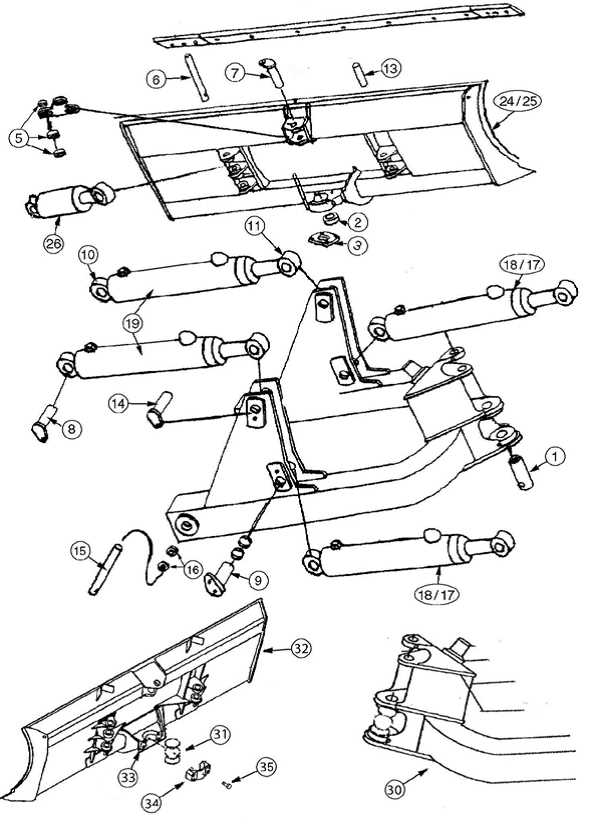
Regular upkeep of machinery is essential for optimal performance and longevity. Understanding which components frequently require replacement can help ensure efficient operation and prevent unexpected breakdowns. This section provides insights into commonly substituted elements and practical advice for maintenance to keep your equipment in peak condition.
- Filters: Air, oil, and fuel filters should be replaced regularly to maintain engine efficiency and prevent contamination.
- Batteries: Check the battery condition periodically and replace it as needed to avoid starting issues.
- Belts: Inspect drive belts for wear and tension. Replace them if they show signs of cracking or fraying.
- Fluids: Regularly check and change engine oil, hydraulic fluid, and coolant to ensure proper function and prevent overheating.
- Tires: Monitor tire pressure and tread wear. Rotate or replace tires to ensure safe operation and optimal traction.
In addition to replacing specific components, consider the following maintenance tips:
- Conduct routine inspections to identify wear and tear early.
- Follow the manufacturer’s service schedule for replacements and checks.
- Keep the machinery clean to prevent dirt accumulation, which can cause premature wear.
- Ensure that all fasteners are tightened to specifications to prevent loosening during operation.
- Maintain a record of replacements and service activities to track maintenance history effectively.
By staying proactive about maintenance and understanding which elements are likely to need replacement, operators can enhance the reliability and efficiency of their machinery.