Spinning Wheel Parts Diagrams and Their Functions

In wheel

parts of a spinning wheel diagrams

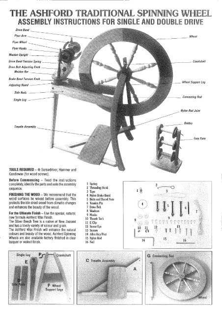
In many traditional crafting techniques, various mechanical instruments play a vital role in creating textiles. Understanding the individual elements of these tools is essential for anyone looking to master the art of yarn production. Each section of the device has its unique function, working together harmoniously to transform fibers into thread.

By exploring these structures, we can better appreciate the balance between form and function that these devices exhibit. Whether used by artisans or hobbyists, their intricate design reflects centuries of refinement. Recognizing how each piece contributes to the overall process provides valuable insights into this timeless craft.

Understanding Spinning Wheel Mechanics
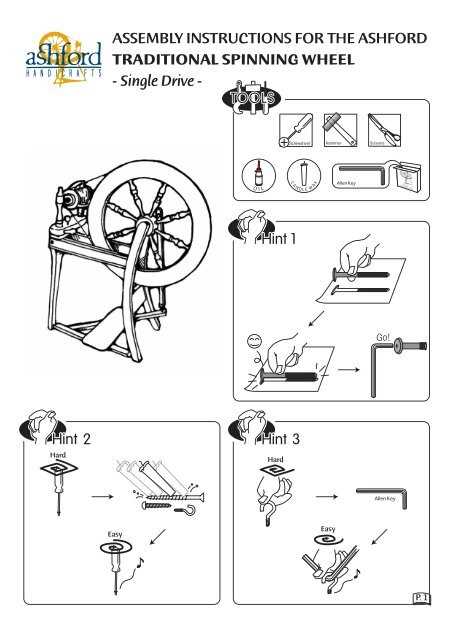
parts of a spinning wheel diagrams

The intricacies of fiber crafting devices rely on a balance between multiple interconnected elements, working together to transform raw materials into thread. To fully grasp how these mechanisms function, it is essential to consider their coordination, movement, and efficiency.

Key Functions and Their Roles

Various parts of the system contribute to the seamless operation of the whole process. Each component plays a crucial role in the transformation, regulating tension, twist, and motion. These functions are harmonized, ensuring smooth operation and high-quality results.

Mechanical Coordination

Effective synchronization is critical to maintaining stability and efficiency. The harmonious interaction of the system’s components ensures continuous motion, allowing for uniform production. Any disruption in this coordination can affect the final outcome.

Main Components and Their Functions

parts of a spinning wheel diagrams

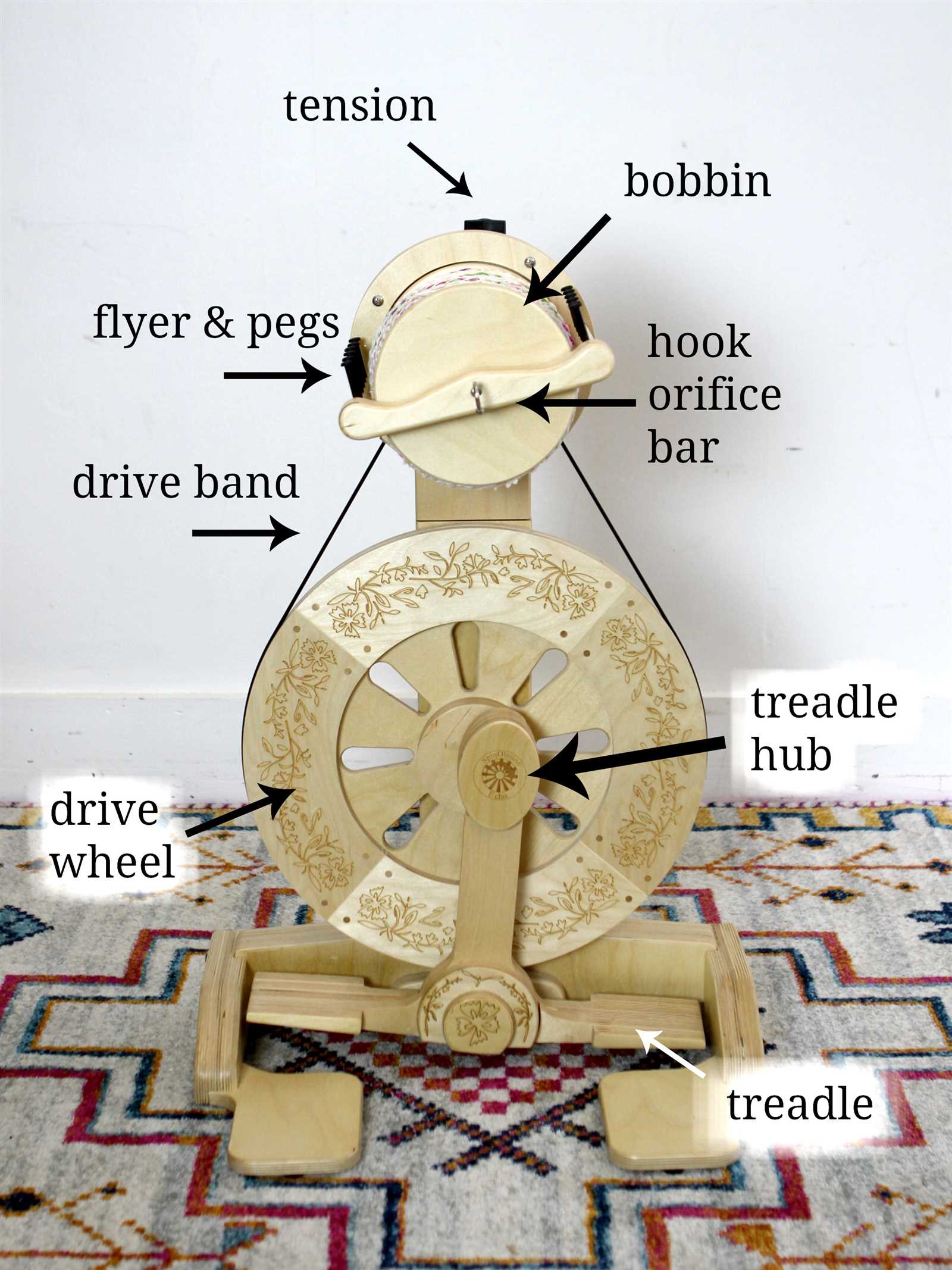
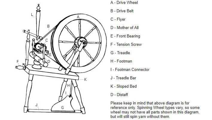
The structure of traditional crafting devices includes several interconnected elements, each playing a key role in ensuring smooth operation. Understanding these elements helps in grasping the overall function of the tool, allowing for better control and maintenance. Below is an overview of the essential components and their primary purposes.

Component Function
Drive System Initiates movement, ensuring consistency in operation.
Tension Adjuster Controls the amount of pull on the material, influencing its final texture.

The Role of the Drive Wheel

The central function of this crucial component is to control the rotation and speed of the device. Its smooth operation ensures consistent motion, which directly affects the overall performance and output quality. Understanding its role is key to maintaining efficiency and precision during use.

How It Works

By converting energy into motion, the drive wheel sets the mechanism in motion, synchronizing other elements. Its construction and size directly influence the tempo and fluidity, allowing for adjustments that cater to different needs. Proper alignment and calibration are essential for maximizing effectiveness.

Maintenance Tips

parts of a spinning wheel diagrams

Regular care is required to prevent wear and tear. Lubricating the axle, checking for alignment issues, and ensuring balanced rotation will extend its lifespan. Additionally, keeping it clean from debris is crucial for smooth functionality.

Component Function
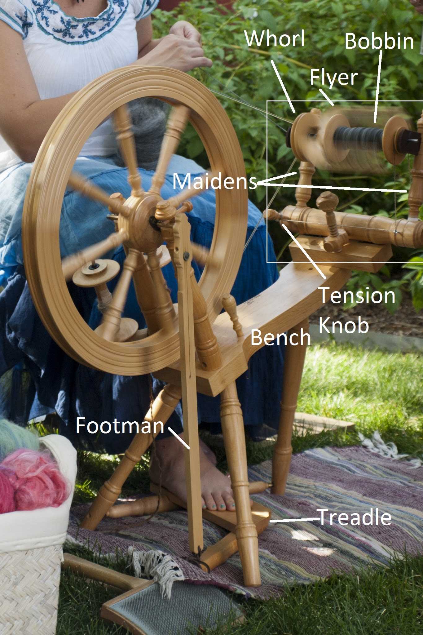
Flyer This part rotates to guide and twist fibers, ensuring consistent tension as material is drawn in.
Bobbin Used to collect and store the spun material as it is twisted, controlling the speed of winding.
Treadle Activated by foot, it powers the mechanism, allowing hands-free control over the process.
Whorl Works in tandem with the drive system to regulate the speed of rotation, affecting the twist strength.
Drive Band
Maintenance Task Recommended Frequency
Lubrication Every

Importance of the Tension Adjustment

parts of a spinning wheel diagrams

Proper regulation of tension is essential to ensure a smooth and consistent flow during operation. The balance achieved through adjusting the tension impacts both the quality and speed of the process, influencing the overall outcome. Without the right balance, there can be disruptions that may lead to uneven results or inefficiencies.

Achieving consistency is key when managing tension. By fine-tuning this aspect, one can maintain steady performance, preventing breaks or irregularities. The right tension helps control not only the pace but also ensures that the outcome remains uniform and high-quality.

Precision is crucial in maintaining the correct tension settings, as even minor adjustments can have significant effects. It’s important to monitor this closely to ensure optimal functionality and to reduce unnecessary strain or wear during extended use.

How the Flyer Mechanism Operates

parts of a spinning wheel diagrams

The flyer system is a crucial element in transforming fibers into continuous thread. Its design allows for efficient rotation and distribution of the material during the process, ensuring an even and consistent output. By controlling the tension and twist, the device ensures a uniform result throughout the process.

The core function relies on a coordinated movement between the rotating arms and the bobbin, which collect the material into a controlled loop. This interaction regulates the thickness and tightness of the final product, making the flyer essential for both accuracy and quality.

Component Function
Arms Control the rotation and direction of the fibers.
Bobbin Collects the material and determines its tension.
Hooks Guide

The Functionality of the Bobbin and Spindle

parts of a spinning wheel diagrams

The components responsible for twisting fibers into a cohesive strand are essential in the textile production process. These elements work in tandem, each playing a distinct role in the creation of yarn, ensuring efficiency and consistency in the final product.

The bobbin serves as a crucial reservoir for the gathered material, allowing for uninterrupted production. Its design enables easy loading and unloading, while also maintaining the tension needed for effective operation. Here are some key functions of the bobbin:

  • Stores the spun fiber securely.
  • Facilitates smooth delivery to the processing mechanism.
  • Allows for quick changes during production without significant downtime.

In contrast, the spindle acts as the driving force, manipulating the fiber into the desired form. This component provides the necessary rotation and tension, contributing to the overall quality of the yarn produced. The primary roles of the spindle include:

  • Generating the rotational motion needed for twisting.
  • Controlling the fiber tension throughout the process.
  • Ensuring uniformity in the thickness of the resulting strand.

Together, these two components are vital for achieving high-quality outcomes in fiber processing. Their combined functionalities ensure that each stage of production operates smoothly and efficiently.

Exploring the Double Drive System

The double drive mechanism is a fascinating feature that enhances the efficiency and versatility of fiber processing tools. This system allows for the simultaneous operation of multiple components, facilitating smoother transitions and greater control during the crafting process.

Advantages of the Double Drive Mechanism

parts of a spinning wheel diagrams

  • Improved speed control, allowing for adjustments based on the desired thickness of the yarn.
  • Enhanced power transmission, enabling smoother operations even with varying fiber types.
  • Increased versatility, accommodating various techniques and materials with ease.

How the Double Drive Works

The mechanism operates by utilizing two separate drive bands, each serving distinct functions within the system. This configuration allows for:

  1. Independent control of the flyer and bobbin, resulting in optimized tension and twist.
  2. Seamless switching between different crafting methods without the need for significant adjustments.

By understanding the intricacies of this dual drive approach, artisans can maximize their creative potential and enhance their overall crafting experience.

Foot Pedal and Its Control in Spinning

parts of a spinning wheel diagrams

The foot pedal serves as a crucial mechanism in the operation of a textile crafting device, allowing the user to regulate the speed and rhythm of the thread production process. By utilizing this component, artisans can achieve a seamless flow of fibers, enhancing both efficiency and creativity during their work.

Functionality of the Foot Pedal

parts of a spinning wheel diagrams

This control element enables the operator to initiate and halt the movement effortlessly. By pressing down on the pedal, one can increase the motion, while releasing it allows for a gentle deceleration. This dynamic interaction fosters greater precision and adaptability, essential for achieving the desired results.

Technique and Coordination

Mastering the use of the foot pedal requires practice and coordination. The artisan develops a sense of timing and responsiveness, ensuring that the tension of the threads remains consistent. With experience, the operator can perform intricate tasks, manipulating the pedal to create various textures and patterns in the final product.

The Relationship Between the Orifice and Yarn Tension

The interaction between the exit point and the stress of the fiber being produced plays a crucial role in the overall quality of the final product. Understanding this connection is essential for achieving optimal results in the crafting process. The design of the exit point significantly influences how the material behaves as it is drawn through, affecting not only the tension but also the consistency of the output.

Impact of Orifice Size

The dimensions of the exit point directly influence the fiber’s tension. A larger opening can lead to a looser draw, which may result in uneven thickness and lower strength. Conversely, a smaller orifice may increase tension, leading to finer, more consistent strands. Adjusting the orifice size allows artisans to manipulate the characteristics of the yarn being produced.

Tension Adjustments and Techniques

To maintain the desired tension while utilizing different orifice sizes, various techniques can be employed. Adjusting the braking system or modifying the tensioning devices can help balance the draw. Additionally, experimenting with different materials and their inherent properties can lead to improved outcomes in tension management.

Orifice Size Tension Level Yarn Characteristics
Large Low Thicker, less consistent
Medium Moderate Balanced thickness and strength
Small High Finer, more uniform