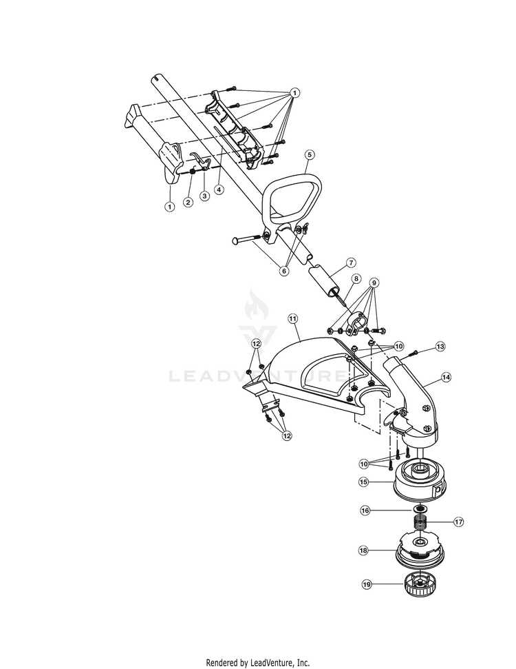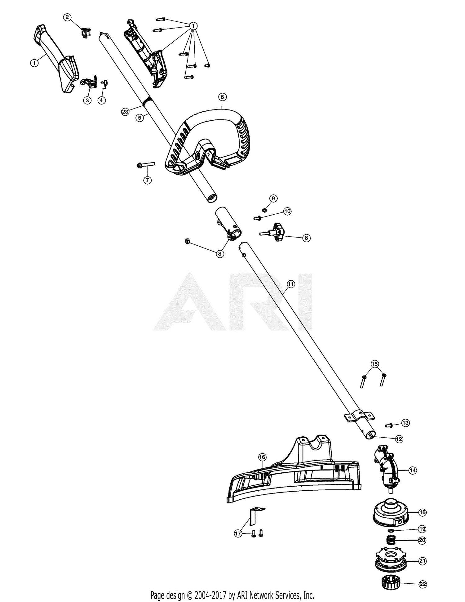
When it comes to maintaining efficient performance, knowing the individual elements that make up your outdoor power machine is crucial. Each part plays a role in ensuring smooth operation, making it essential to understand how these elements connect and function together.
Proper upkeep requires a detailed understanding of the different components. Identifying and replacing these elements when needed ensures that your equipment operates reliably over time. By being familiar with the internal structure, you can address issues before they lead to bigger problems.
Whether you are a seasoned professional or a casual user, understanding the fundamental parts of your tool is key to keeping it in top condition. Knowing how these pieces fit into the bigger system allows for smoother maintenance and repair processes, extending the life of your machine.
Troy-Bilt TB35EC: Key Components Overview
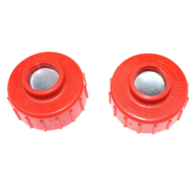
The engine-powered equipment relies on various essential elements working together to ensure efficient operation. These components are designed to interact seamlessly, providing the necessary force and functionality to carry out demanding tasks. Understanding how each part functions within the system is crucial for proper maintenance and maximizing the machine’s performance.
Engine and Power Unit
The heart of the device is the power source, which is responsible for generating the energy needed to drive the equipment. This engine transforms fuel into mechanical force, allowing the machine to operate effectively. Proper care of this unit, including regular maintenance and inspection, ensures longevity and stable performance.
Cutting and Trimming Mechanisms
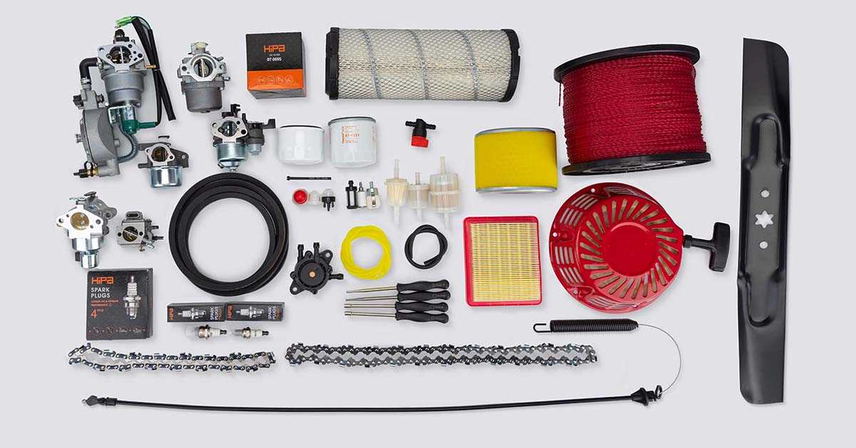
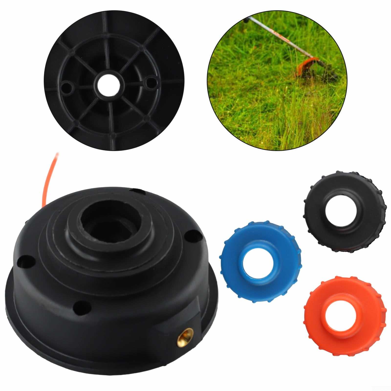
The cutting elements are key for the tool’s primary function. These precision-designed components handle the workload, allowing for clean and efficient cutting. The system that controls their operation must be kept in optimal condition to ensure smooth and reliable performance during use. Regular sharpening and cleaning are recommended for the best results.
Engine Structure and Main Features
The structure of the engine is designed to provide optimal performance, combining efficiency and durability. Key elements of the system work together to ensure smooth operation, while innovative features improve usability and reduce maintenance needs. This balance of robust construction and thoughtful design helps ensure the motor runs reliably, even under challenging conditions.
Core Components
At the heart of the engine, several essential parts work in harmony to deliver power. These include the combustion system, cooling mechanism, and various moving components that convert energy into motion. Each of these parts is constructed with precision, allowing the engine to perform consistently over time.
Advanced Features
Modern engines are equipped with several advanced features aimed at improving overall function. Enhanced fuel efficiency, reduced emissions, and user-friendly starting mechanisms are some of the innovations integrated into the design. These improvements not only benefit the environment but also make the engine easier to operate and
Fuel System: Key Parts and Functions
The fuel system plays a vital role in the operation of any gas-powered equipment. Its primary responsibility is to ensure the smooth delivery of fuel from the tank to the engine, allowing for efficient combustion and reliable performance. Each component of this system works together to manage fuel flow and ensure the proper mix of air and fuel reaches the engine for optimal power generation.
| Component | Function | ||||||||||||||||||||||||||
|---|---|---|---|---|---|---|---|---|---|---|---|---|---|---|---|---|---|---|---|---|---|---|---|---|---|---|---|
| Fuel Tank | Stores fuel for use during operation, ensuring a consistent supply to the engine. | ||||||||||||||||||||||||||
| Fuel Filter | Removes impurities from the fuel to protect the engine and other system components from damage. | ||||||||||||||||||||||||||
| Carburetor | Mixes air and fuel in the correct ratio before sending the mixture to the engine for combustion. | ||||||||||||||||||||||||||
| Fuel Line | Transfers fuel from the tank to the carburet
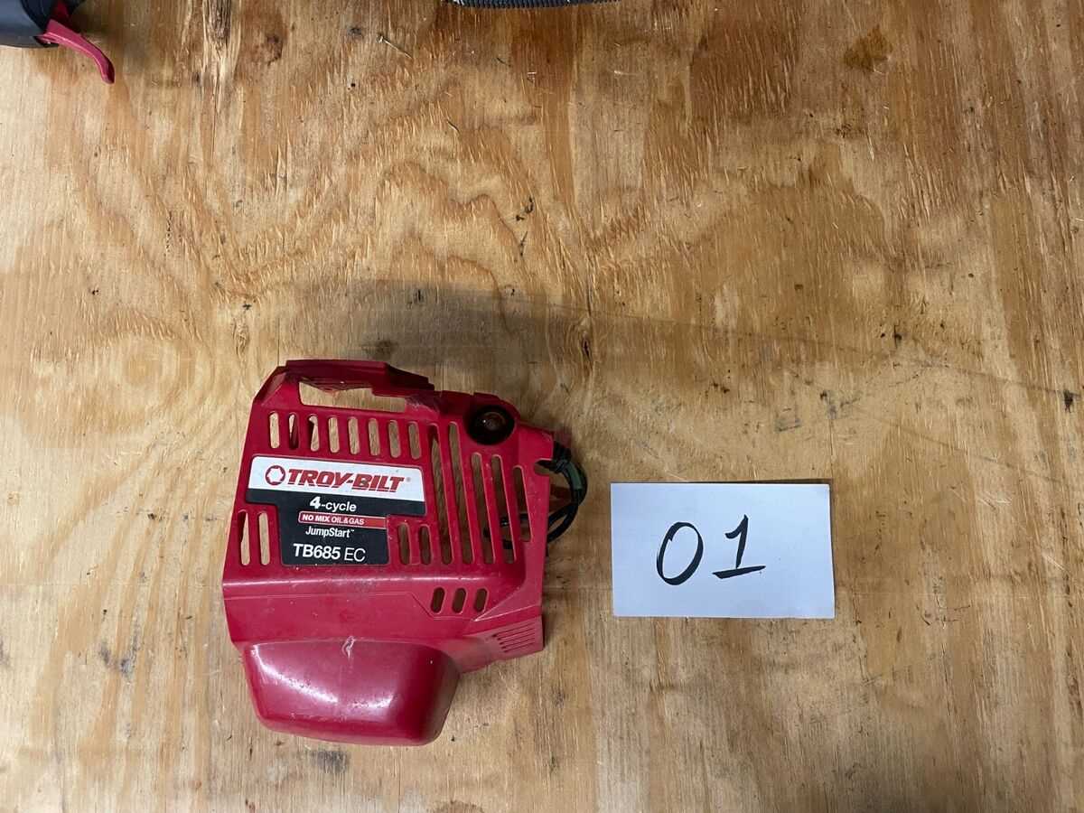
Starter Assembly: Breakdown of ComponentsThe starter mechanism is a critical element in ensuring the smooth operation of various power tools. It consists of several interconnected components that work together to initiate the engine. Understanding the structure of this assembly helps in maintaining and troubleshooting the device efficiently. Main Components of the Starter System
Handle and Throttle Control MechanismThe handle and throttle system ensures smooth operation by allowing precise control of speed and power. This mechanism plays a crucial role in adjusting the output based on user input, providing a comfortable and efficient experience. Properly understanding its components and functionality helps in maintaining steady and safe operation. Main Components of the Control System
The mechanism primarily includes the handle, grip, and throttle lever. The grip provides a firm hold, while the throttle lever allows for easy adjustment of the engine’s speed. These components work together to transmit user input directly to the engine, controlling the acceleration smoothly. Function and AdjustmentThe throttle control links directly to the engine’s control cable, which adjusts the air-fuel mixture. Proper adjustment of this mechanism ensures that the power output responds accurately to the throttle’s position. Regular inspection of the handle and throttle components is important for safe and efficient operation.
Maintenance Tips
Proper maintenance of the cutting head is essential for optimal performance. Here are some practical suggestions:
Air Filter Assembly: Parts and Cleaning
The air filter assembly is a crucial component for maintaining optimal engine performance. It serves as a barrier against dust, debris, and contaminants, ensuring that only clean air enters the combustion chamber. Regular inspection and maintenance of this assembly are essential for prolonging the life of the engine and enhancing efficiency. The assembly typically consists of several key components, including the filter element, which captures impurities, and the housing, which protects the filter and connects it to the engine. Other elements may include gaskets that create a tight seal and clips or fasteners that secure the assembly in place. Each part plays a vital role in the overall functionality of the air intake system. Cleaning the air filter is an important maintenance task that can significantly improve performance. Depending on the type of filter, cleaning may involve rinsing it with water or using compressed air to remove dirt and debris. It is recommended to inspect the filter regularly and replace it if it shows signs of wear or damage, ensuring the engine operates smoothly and efficiently. Drive Shaft Components and StructureThe drive shaft is a crucial element in the transmission of power from the engine to the various working parts of outdoor equipment. Its design is engineered to withstand significant forces and vibrations while ensuring efficient torque transfer. Understanding the various components that make up the drive shaft assembly is essential for effective maintenance and repair. Key ComponentsAmong the primary components of a drive shaft are the universal joints, which allow for flexibility and movement at angles. These joints are essential for accommodating the varying positions of the engine and attachments during operation. Additionally, the yoke plays a vital role, connecting the drive shaft to the transmission and facilitating smooth power delivery. Structural Integrity
The structural integrity of the drive shaft is ensured through materials that provide both strength and lightweight characteristics. Components are typically manufactured from high-grade steel or aluminum alloys, offering durability and resistance to wear. Proper alignment and secure fastening of the drive shaft assembly are also crucial to prevent vibrations and enhance overall performance. Ignition System: Components and FunctionalityThe ignition system is a critical component in the operation of various small engines, responsible for generating the spark necessary for combustion. This system includes multiple elements that work together to ensure reliable starting and optimal engine performance. Understanding each part’s role provides insights into how ignition systems function effectively, contributing to the overall efficiency of the machinery. Main ComponentsThe ignition system comprises several essential parts, each playing a vital role in initiating the combustion process. These components include the ignition coil, spark plug, ignition module, and wiring harness. Each part must function correctly to create the spark that ignites the fuel-air mixture in the engine’s combustion chamber.
Functionality Overview
When the ignition system is activated, the ignition coil receives power from the battery and converts it to a high voltage. This high voltage is sent to the spark plug, where it creates a spark that ignites the fuel-air mixture. The ignition module plays a crucial role by regulating when the spark occurs, ensuring that it happens at the optimal point in the engine’s cycle for maximum efficiency. Proper functioning of all these components is essential for reliable engine operation and performance. |
