
Understanding the structure and assembly of outdoor machinery is essential for efficient maintenance and repair. Proper knowledge of the various sections and individual elements ensures smooth operation and prolongs the lifespan of the device. With clear visual references, users can identify the specific parts that require attention, whether for replacement, lubrication, or adjustment.
Accurate identification of each segment allows for a more effective approach to upkeep, minimizing the risk of errors during disassembly or reassembly. Every tool has a unique configuration, with several crucial pieces working together to optimize performance. Having a reference that displays these components in a clear, organized manner is key to achieving this goal.
Detailed illustrations are invaluable in providing a roadmap for users, helping them follow correct procedures and avoid common mistakes. This guide serves as an essential resource for anyone looking to maintain their equipment, ensuring that all necessary parts are easily accessible and correctly installed. Whether you’re a professional or a hobbyist, understanding these details will greatly improve your overall experience with the tool.
Overview of Stihl KM131R Components
The powerful multi-tool engine is built with a variety of key elements that work together to ensure smooth operation and exceptional performance. Understanding the fundamental components is essential for proper maintenance, repair, and overall efficiency. From the power unit to the attachment coupling system, each piece plays a crucial role in achieving optimal functionality.
Engine: The heart of the machine, the engine delivers the necessary power to drive the tool. It includes various sub-components such as pistons, cylinders, and spark plugs, all of which contribute to fuel combustion and efficient energy transfer.
Drive Shaft: This long, sturdy component transmits the rotational force from the engine to the various attachments. It must be robust to withstand the stress and force applied during operation.
Coupling System: Located at the front end, this system allows for easy attachment and detachment of different tools, such as trimmers, edgers, and blowers. The coupling mechanism ensures a secure fit, providing stability during use.
Fuel Tank: The fuel tank stores the necessary fuel mixture for the engine. Proper maintenance and regular checks are critical to avoid clogging or damage that could impact engine performance.
Throttle and Controls: The throttle is responsible for regulating engine speed, and other control mechanisms allow the user to manage functions such as on/off or idle modes. These components must remain responsive and functional for safe operation.
Each of these elements works in tandem to deliver a versatile and powerful tool. Regular inspection and knowledge of the individual components will enhance the longevity and efficiency of the device.
Understanding the Parts Layout for Efficient Repairs
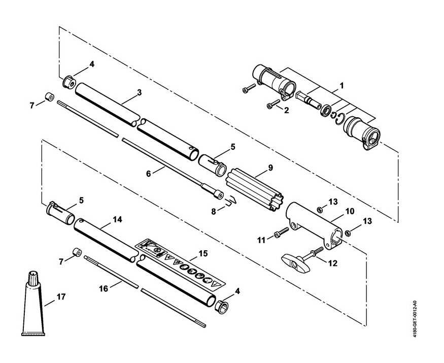
Grasping the configuration of components is crucial for streamlined maintenance and effective troubleshooting. A clear understanding of how different elements interconnect not only facilitates quicker repairs but also enhances the overall performance of the equipment. By familiarizing oneself with the arrangement of these elements, users can save time and reduce frustration during the repair process.
Key Components Overview
Identifying the main segments involved in the machinery can provide insights into potential issues. Below is a table that outlines the primary sections and their functions, aiding in a better understanding of the overall system.
| Section | Function |
|---|---|
| Engine Assembly | Drives the operational mechanisms |
| Fuel System | Stores and supplies fuel to the engine |
| Transmission | Transfers power from the engine to the working tools |
| Handlebar | Provides control and stability during operation |
Benefits of Understanding Component Layout
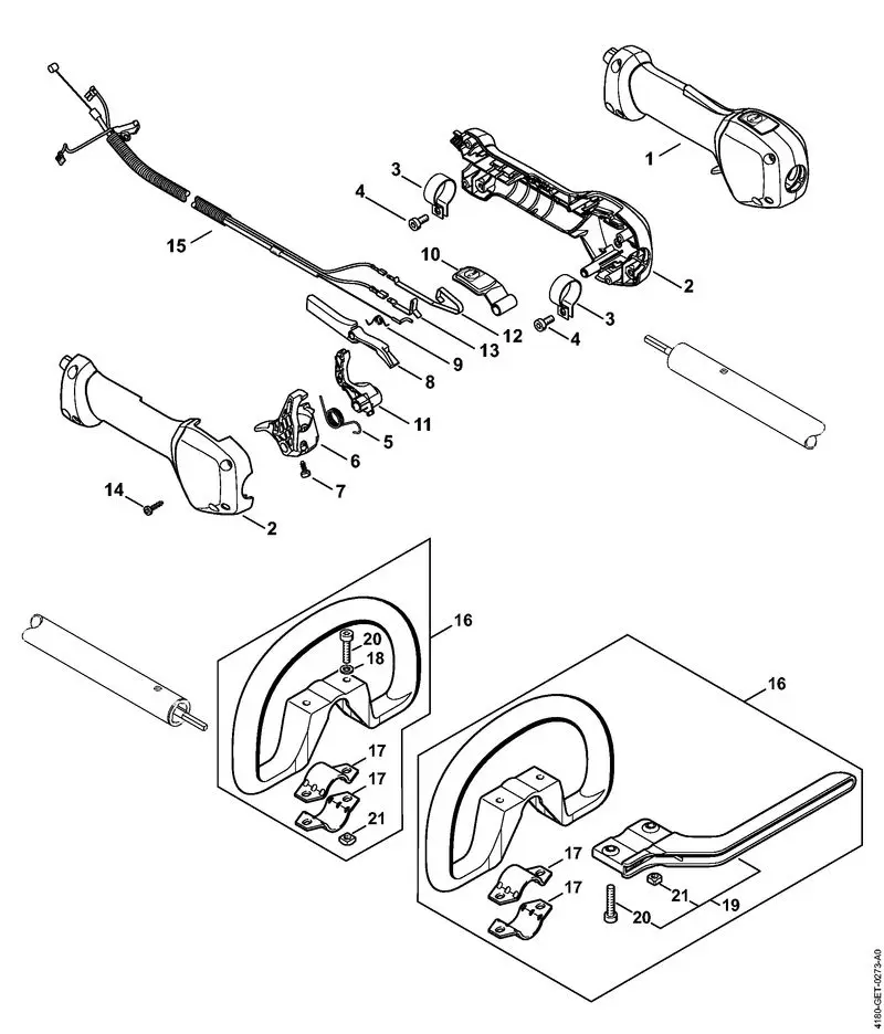
Acquaintance with the structure not only empowers users to carry out repairs more efficiently but also fosters a deeper appreciation for the machinery’s functionality. This knowledge can lead to proactive maintenance practices, ultimately extending the lifespan of the equipment and enhancing its operational reliability.
How to Identify Each Part in the Diagram
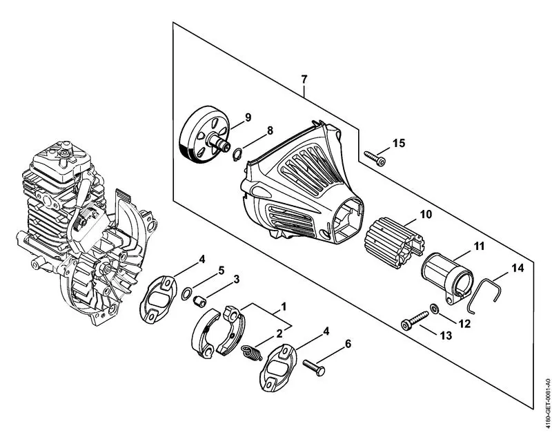
Understanding the various components of a tool is essential for effective maintenance and repairs. Each element plays a crucial role in the overall functionality, and recognizing them can simplify the process of assembly and disassembly. This guide provides a clear method for identifying the individual segments shown in the visual representation.
| Component | Description | Function |
|---|---|---|
| Engine Housing | The main outer shell that encases the engine | Protects internal components and houses essential parts |
| Throttle Control | A lever or trigger used to adjust power output | Regulates engine speed and tool operation |
| Fuel Tank | Container for holding fuel | Supplies energy to the engine for operation |
| Cutting Attachment | The implement that performs the cutting action | Executes the primary task of trimming or cutting |
| Handle | The grip used to control the tool | Provides maneuverability and control during use |
By familiarizing yourself with each of these components, you’ll be better equipped to troubleshoot issues and ensure proper functionality of the equipment. Taking time to study each segment will enhance your overall proficiency and confidence in handling the tool.
Commonly Replaced Parts in the Stihl KM131R
In any piece of equipment, certain components are more prone to wear and tear due to their frequent use and the demands of various tasks. Understanding which elements typically require replacement can enhance the longevity and performance of your machine. This section outlines the components that users often find themselves replacing to maintain optimal functionality.
- Trimmer Head: A critical element for cutting, it often experiences wear from regular use.
- Air Filter: Essential for maintaining engine efficiency, this part can become clogged over time, impacting performance.
- Spark Plug: This component plays a vital role in starting the engine and may require replacement after extended use.
- Fuel Filter: To ensure proper fuel flow, this filter is crucial and should be checked regularly for blockages.
- Starter Rope: Due to repeated pulling, this part may fray or break, necessitating a replacement.
- Drive Shaft: As a key component for power transmission, any damage can lead to performance issues.
Regular maintenance and timely replacement of these components can significantly improve the operational life and efficiency of your equipment. Familiarizing yourself with these common replacements will help you keep your machine running smoothly.
Step-by-Step Guide to Using the Parts Diagram
Understanding the layout and components of your equipment can greatly enhance maintenance and repair efficiency. Utilizing a visual representation of the various elements can streamline the process, ensuring you identify and acquire the correct pieces without confusion.
1. Familiarize Yourself with the Layout
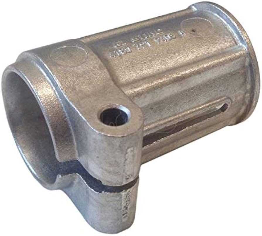
Begin by examining the overall structure presented in the visual aid. Take note of the different sections and how they are categorized. This will help you to quickly locate specific areas of interest, whether for routine maintenance or replacement purposes.
2. Identify and Match Components
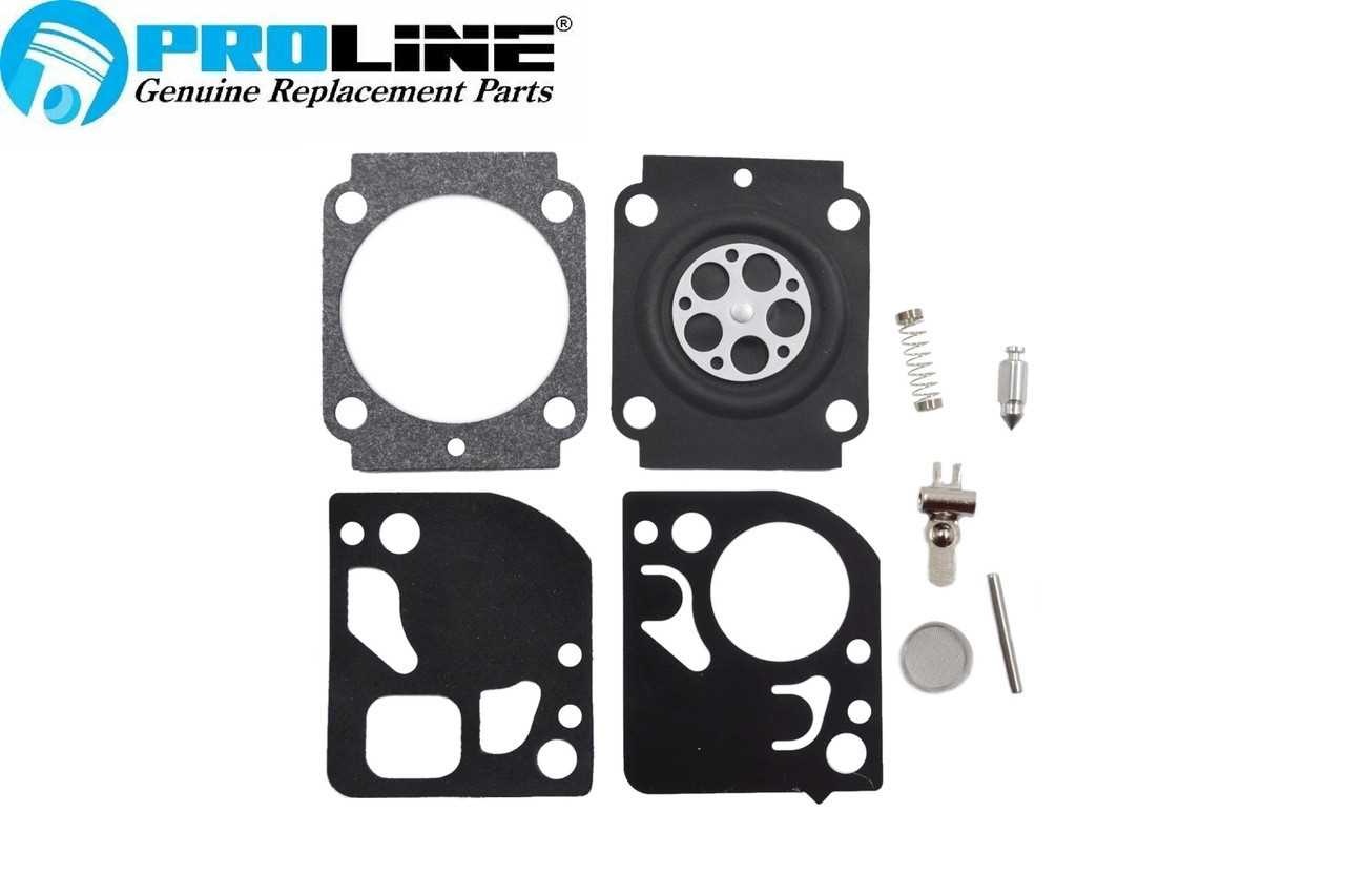
Once you have a grasp of the layout, start matching the labeled elements with your equipment. Cross-reference these labels with your own machine to pinpoint exactly what you need. If any part is damaged or requires replacement, the visual guide will make it easier to find the correct alternative. Remember to pay attention to any notes or specifications that might indicate compatibility.
Tip: Keep a checklist of the parts you need while you navigate through the visual guide. This will help in streamlining the ordering process and ensuring nothing is overlooked.
Troubleshooting with the Stihl KM131R Parts Diagram

When dealing with equipment maintenance, understanding the components and their relationships is crucial for effective problem resolution. A visual representation of the various elements can significantly enhance your ability to diagnose issues and implement solutions.
Common problems often stem from a few specific areas. By referencing the schematic, users can systematically identify the source of the malfunction. Here are some frequent issues and their potential causes:
- Engine won’t start:
- Check fuel levels and quality.
- Inspect the spark plug for wear or damage.
- Examine the ignition system for faults.
- Loss of power:
- Look for air filter blockages.
- Assess the carburetor for clogs or misadjustments.
- Evaluate the fuel delivery system.
- Excessive vibration:
- Inspect the blades for damage or misalignment.
- Check mounting points for looseness.
- Review any worn components that may need replacement.
Utilizing the visual guide allows for a more structured approach to troubleshooting. By systematically following the layout, one can pinpoint issues more efficiently. It serves not only as a reference for repairs but also as a valuable educational tool for users looking to deepen their understanding of their machinery.
In conclusion, a clear illustration of the machine’s components can empower users to tackle issues confidently. Familiarity with each part’s function will lead to better maintenance practices and prolonged equipment life.
Where to Find Original Stihl KM131R Parts
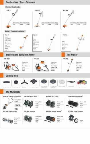
When searching for authentic components for your outdoor power equipment, it’s essential to know the best sources. Genuine replacements ensure optimal performance and longevity, giving you peace of mind while maintaining your tools.
- Authorized Dealers: Visiting an official dealer is one of the most reliable options. They offer a comprehensive selection of genuine items and can assist with specific inquiries.
- Manufacturer’s Website: The official website often has a dedicated section for replacement items. You can find detailed listings and sometimes order directly online.
- Local Hardware Stores: Many hardware stores carry a selection of authentic items. It’s worth checking with nearby retailers that specialize in outdoor equipment.
- Online Retailers: Numerous e-commerce platforms specialize in outdoor gear. Look for reputable sites that guarantee genuine merchandise.
- Forums and Community Groups: Joining online forums or local community groups focused on outdoor maintenance can provide insights and recommendations for sourcing authentic components.
Using these sources will help ensure you receive high-quality replacements that maintain the efficiency and reliability of your equipment.
Tips for Ensuring Proper Assembly After Replacement
When undertaking maintenance or repairs, ensuring correct reassembly is crucial for optimal performance and safety. Following a few key practices can significantly enhance the reliability of the equipment and prolong its lifespan. Understanding the components and their functions can aid in this process.
1. Reference the Manual: Always consult the user manual for specific instructions and diagrams. These resources provide valuable information about the arrangement and orientation of each part, making it easier to piece everything back together correctly.
2. Organize Your Workspace: Keep your workspace tidy and organized. Lay out all components in an orderly fashion, which will help prevent misplacement and confusion during the reassembly process.
3. Clean Components: Before reassembling, ensure that all parts are clean and free from debris. This can prevent damage and ensure a better fit, reducing the likelihood of operational issues.
4. Double-Check Compatibility: Confirm that the replacement components are compatible with your equipment. Using mismatched parts can lead to malfunction or even safety hazards.
5. Follow a Systematic Approach: Reassemble components in a logical sequence. Start from the base and work your way up, ensuring each part is securely fastened before moving to the next.
6. Test After Assembly: Once everything is back in place, conduct a thorough inspection and test the equipment in a controlled environment. Monitor for any unusual noises or vibrations that may indicate an assembly issue.
By adhering to these guidelines, you can achieve a successful reassembly and ensure that your equipment operates smoothly and efficiently.