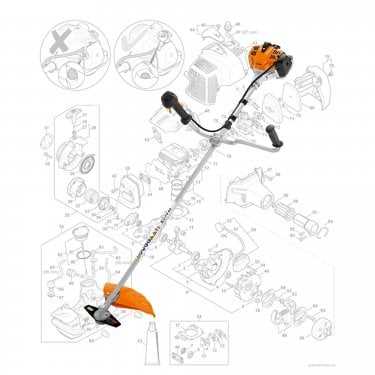
Stihl FS 55 R Parts Diagram Overview

In stihl

stihl fs 55 r parts diagram

The maintenance of any grass trimmer requires a thorough understanding of its internal elements and structure. This knowledge ensures smooth performance, long-lasting durability, and proper upkeep. Being aware of each essential piece helps users manage repairs efficiently, even when challenges arise.

Every machine, regardless of its complexity, is made up of a variety of interconnected elements that serve different roles. Identifying these key components can aid in troubleshooting and optimizing usage, especially when some elements show signs of wear. Learning the functions of different mechanisms is a crucial step toward reliable operation.

Overview of Key Components

The equipment relies on several essential elements that ensure its functionality and efficiency. These components are designed to work in harmony, contributing to the overall performance and longevity of the tool.

  • Engine: The motor provides the power needed for the machine to operate, delivering consistent energy output during use.
  • Fuel System: This system manages the flow of fuel, ensuring proper combustion and optimal energy transfer.
  • Handle: Designed for comfort and control, the handle allows for precise movements and easy handling.
  • Cutting Mechanism: The cutting component plays a crucial role in performing the primary task, with different designs available depending on the type of work.
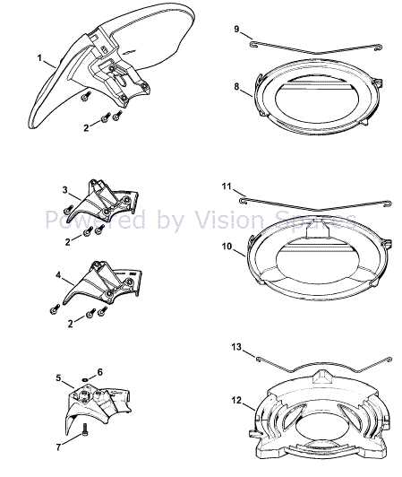
  • Protective Guard: A shield that prevents debris from causing harm during operation, ensuring user safety.
  • Throttle Assembly and Control Details

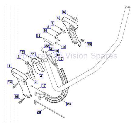
    The throttle mechanism plays a crucial role in managing the engine’s speed and overall performance. Proper control of this system ensures smooth operation and safe handling during use. In this section, we will explore the key components involved in throttle control and their respective functions, ensuring optimal machine responsiveness.

    Main Components of the Throttle System
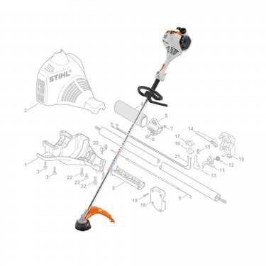
    stihl fs 55 r parts diagram

    The throttle assembly includes several interconnected elements that work together to regulate power delivery. These components must function in harmony to ensure the engine responds accurately to user input. Understanding how each part contributes to the overall control system is vital for maintaining proper functionality.

    Throttle Cable and Handle Functions

    The throttle cable connects the control handle to the engine, transmitting signals from the user to adjust power levels. The handle itself offers intuitive control, allowing easy adjustments during operation. A well-maintained cable ensures quick and precise throttle response, enhancing the equipment’s efficiency.

    Fuel System Structure and Parts

    The fuel system plays a crucial role in ensuring proper engine operation. It is responsible for delivering a balanced mixture of fuel and air to the combustion chamber, which allows for efficient performance. Understanding the components that make up this system is essential for maintaining the engine’s functionality.

    Fuel Tank: This container holds the fuel before it is drawn into the system. It is usually designed to ensure a steady supply of fuel to the engine.

    Carburetor: The carburetor mixes air with fuel in the correct proportion. It ensures the engine receives the optimal blend to achieve efficient combustion.

    Fuel Filter: Positioned between the tank and the carburetor, the filter removes impurities from the fuel, preventing blockages and ensuring clean fuel reaches the engine.

    Fuel Lines: These tubes transport the fuel from the tank to the carburetor. They must be kept in good condition to avoid leaks or obstructions.

    Each of these elements is essential for the smooth operation of the equipment, and regular maintenance of these components can extend the lifespan of the engine.

    Cutting Blade Mechanism Explained

    stihl fs 55 r parts diagram

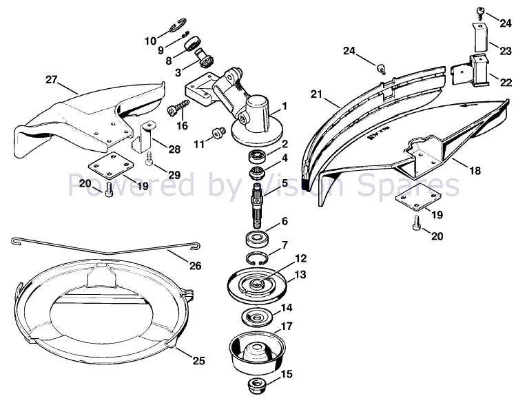
    The cutting blade mechanism is a vital component that ensures efficient vegetation trimming. This system operates by translating rotational energy into cutting action, making it an essential part of any tool used for clearing overgrown areas. Understanding the basic working principles helps to maintain performance and safety during operation.

    Main Components of the Mechanism

    At the core of the blade mechanism are several interconnected parts that work together to provide smooth cutting. These elements include the rotating drive shaft, blade attachment system, and safety guards, all of which play key roles in ensuring precision and control.

    Blade Types and Functionality

    There are different blade types designed for specific applications, each varying in shape and material. The selection of the correct blade influences the overall cutting efficiency and can be tailored to the vegetation type and density.

    Component Function
    Throttle Cable

    Engine Parts and Their Functions

    The internal mechanism of a gasoline-powered tool relies on several components working together to ensure smooth operation. Understanding the individual elements of the motor and their specific roles helps in maintaining and troubleshooting the equipment effectively. Each part has a crucial role, contributing to the overall performance and efficiency of the machine.

    Core Components

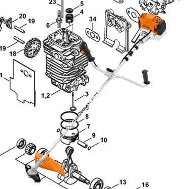
    The motor consists of several essential elements that drive the system. The cylinder houses the combustion process, where fuel ignites to generate power. Inside, the piston moves up and down, converting the energy from combustion into mechanical force. These movements are transferred to the crankshaft, which creates the rotation needed to operate the tool.

    Supporting Systems

    stihl fs 55 r parts diagram

    In addition to core components, other systems support the functioning of the engine. The carburetor mixes fuel and air in the right proportions before it enters the combustion chamber. The spark plug ignites the air-fuel mixture, ensuring continuous power generation. Without

    Air Filter Setup and Maintenance

    stihl fs 55 r parts diagram

    The air filter is a crucial component in ensuring optimal performance and longevity of the equipment. Proper installation and regular upkeep of this element can significantly affect the efficiency and functionality of the engine. It is essential to follow the correct procedures to ensure that the air intake remains unobstructed and clean.

    To set up the air filter, first, ensure that the engine is off and cool. Locate the filter housing and carefully remove the cover. Examine the filter for any signs of damage or excessive dirt. If the filter is reusable, clean it thoroughly with compressed air or wash it in warm, soapy water. Allow it to dry completely before reinstalling. If the filter is damaged or excessively worn, it should be replaced with a new one to maintain optimal airflow and filtration.

    Regular maintenance of the air filter is vital. It is advisable to check the filter periodically, especially after extended use or in dusty conditions. Cleaning or replacing the filter at recommended intervals helps prevent dirt and debris from entering the engine, which can lead to reduced performance and potential damage. Keeping the air filter in good condition ensures efficient fuel consumption and enhances overall engine performance.

    Handlebar Design and Adjustment

    The handlebar of a grass trimmer is crucial for user comfort and control. Its design influences maneuverability and stability during operation, allowing the user to work efficiently over extended periods. Proper adjustment can enhance ergonomics, reducing fatigue and improving precision.

    Design Features

    stihl fs 55 r parts diagram

    • Adjustable height for personalized comfort
    • Curved shape to enhance grip and control
    • Vibration-dampening materials to minimize strain
    • Integrated controls for ease of use

    Adjustment Guidelines

    stihl fs 55 r parts diagram

    1. Check the handlebar height and adjust it according to your stature.
    2. Ensure that the angle of the handlebar aligns with your preferred working position.
    3. Secure all fasteners to maintain stability during operation.
    4. Test the adjustments by performing a brief operation to ensure comfort.

    Starter Mechanism and Repairs

    stihl fs 55 r parts diagram

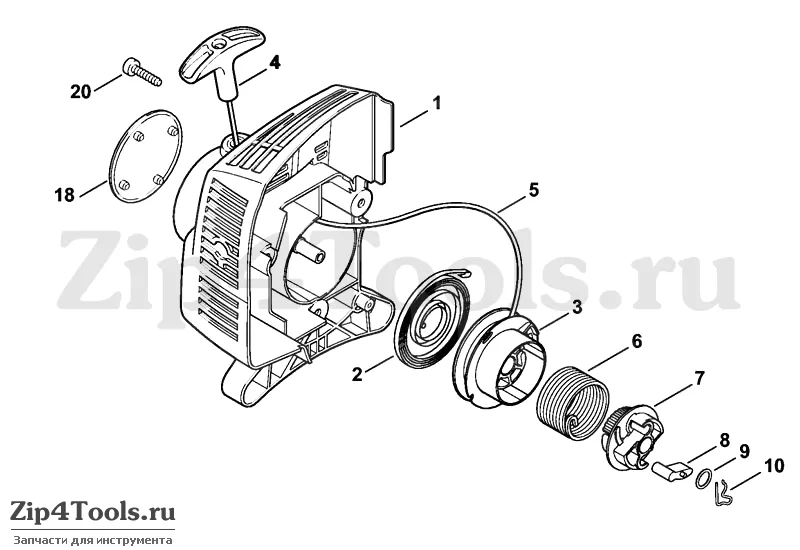
    The starting system of a small engine plays a crucial role in ensuring reliable operation. Understanding its components and their functions can significantly enhance maintenance efforts and reduce the risk of failures.

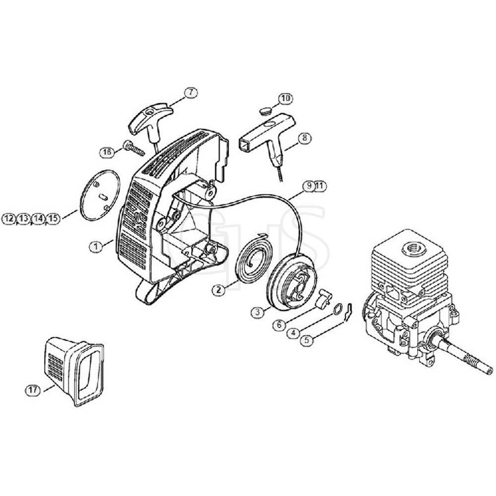
    Components of the Starter Mechanism include the recoil starter, pawls, spring, and rope. Each element contributes to the smooth engagement and disengagement process, facilitating effortless ignition. Regular inspection of these parts helps identify wear and tear, which can lead to malfunctioning.

    Common Repairs often involve replacing frayed ropes, worn-out springs, or faulty pawls. To replace the rope, carefully disassemble the recoil unit, remove the old rope, and install a new one while ensuring proper winding to avoid jamming. Additionally, lubricating the spring mechanism can improve performance and longevity.

    Performing regular checks and maintenance on the starting assembly not only ensures efficient operation but also extends the lifespan of the equipment. A proactive approach to repairs can prevent unexpected breakdowns and enhance overall user satisfaction.

    Shaft and Gearbox Configuration

    The configuration of the shaft and gearbox plays a crucial role in the overall performance of power equipment. This assembly ensures efficient power transfer from the engine to the cutting tool, influencing both functionality and durability. Understanding the components involved and their arrangement is essential for optimal operation and maintenance.

    Components of the Shaft Assembly

    The shaft assembly typically comprises a main shaft, couplings, and bearings. The main shaft serves as the primary conduit for power transmission, while couplings connect various elements securely. Bearings facilitate smooth rotation, minimizing friction and wear during operation.

    Gearbox Functionality

    The gearbox is designed to adjust the rotational speed and torque delivered to the cutting implement. By employing different gear ratios, it enables the equipment to operate effectively across various tasks. A well-maintained gearbox ensures longevity and reliability, contributing to the machine’s overall efficiency.

    Blade Type Ideal Use
    Metal Blades Thicker brush and small shrubs