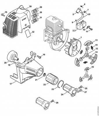
The layout of the various elements in this machine is crucial for its smooth operation and maintenance. Understanding the placement and relationship of each component helps in ensuring proper assembly and troubleshooting. This guide provides a detailed look into how the different pieces are organized, offering valuable insights into their functions.
Each element plays a vital role in the overall performance of the equipment. By familiarizing yourself with the structure, you can make informed decisions regarding repairs or replacements. This organized approach ensures the machine runs efficiently, reducing the likelihood of errors or damage.
Key aspects such as the position of mechanical parts, connections, and assemblies are presented in a logical order to enhance your understanding. By focusing on this detailed breakdown, you gain a clearer perspective on the internal workings of the equipment.
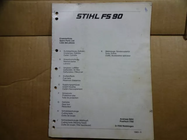
Stihl FS 90 Overview and Key Components
This section provides a detailed look at the features and primary elements that make this model a reliable choice for various outdoor tasks. It is designed for efficiency and durability, ensuring high performance in demanding conditions.
Main Features
- Efficient engine for prolonged use
- Ergonomic design for comfortable handling
- Durable materials for long-lasting operation
Key Mechanical Elements
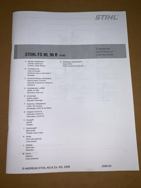
- Power unit ensuring strong cutting force
- Cutting system adaptable to different tasks
- Control handles for easy maneuverability
Understanding the Engine Structure
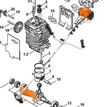
The engine is a crucial component of any cutting tool, designed to provide the necessary power for efficient operation. Its internal setup, though compact, involves a series of interconnected parts that work together to generate energy and transfer it to the cutting mechanism.
Key elements include the cylinder, which houses the combustion process, and the piston, which moves within the cylinder to create compression. The crankshaft transforms the motion into rotational energy, while the carburetor ensures the correct mixture of fuel and air for combustion. All of these components must function in harmony to maintain optimal performance.
Fuel System: Key Elements and Maintenance
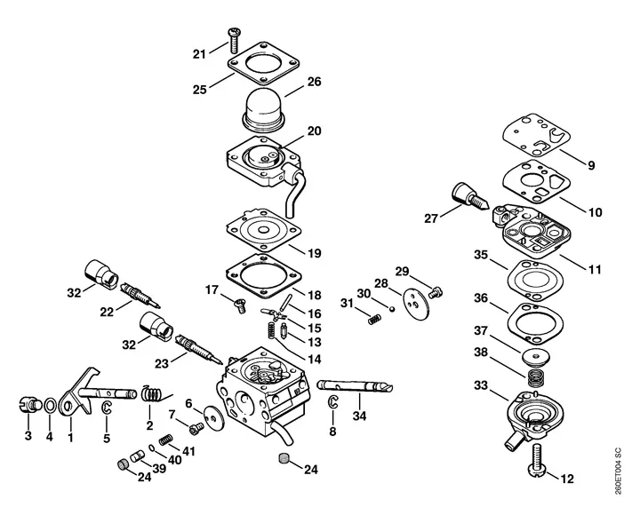
The fuel system plays a crucial role in ensuring smooth engine operation. Regular care and attention to its components are essential to maintain performance and extend the lifespan of the equipment. By understanding the key elements and their proper upkeep, users can prevent common issues and ensure efficient functionality.
Important Components of the Fuel System
The system typically includes the fuel tank, filter, and carburetor. Each part works together to supply the engine with clean, consistent fuel. The filter ensures no debris enters the engine, while the carburetor regulates the fuel-to-air ratio for optimal combustion. Maintaining these elements is essential to prevent performance issues.
Maintenance Tips
Regularly inspecting and cleaning the filter is necessary to avoid clogs. It’s recommended to replace the filter periodically, especially if the equipment is used in dusty conditions. Additionally, carbure
Throttle and Handlebar Assembly Breakdown
The control system and handlebars play a crucial role in ensuring smooth operation and control. This section outlines the structure and function of key elements, providing clarity on how the handle controls work in tandem with the throttle to regulate the machine’s power.
Key Components of the Assembly
- Throttle lever – Controls the speed and power of the engine.
- Handlebar grips – Provides stability and comfort while operating the equipment.
- Cable assembly – Connects the throttle lever to the engine, enabling power regulation.
- Handlebar mounting – Ensures the secure attachment of the handles to the machine.
How It Works
The throttle lever, when pressed, pulls the cable assembly, which adjusts the engine’s power output. Proper alignment of the handlebar ensures comfort and optimal control, making it easier to manage the speed and direction of the equipment.
Air Filtration System Components
The air filtration system plays a crucial role in ensuring that the engine runs efficiently by preventing contaminants from entering the internal components. A well-maintained filtration system not only extends the lifespan of the engine but also improves overall performance.
Filter Element
The core of the air filtration system is the filter element. It traps dust, dirt, and other particles, ensuring that only clean air reaches the engine. This component must be cleaned or replaced regularly to maintain optimal function.
Housing and Seals
The housing encases the filter, protecting it from external elements. Seals ensure that no unfiltered air bypasses the filter, keeping the system airtight and efficient.
- Filter Cover: Provides easy access for maintenance while keeping the filter secure.
- Retaining Clips: Hold the filter in place, preventing movement during operation.
- Air Intake Screen: A secondary barrier that
Cutting Head and Blade Configuration
The selection and arrangement of cutting implements play a crucial role in achieving efficient performance in grass and vegetation management. Understanding the various options available can significantly enhance the effectiveness of the equipment.
Types of Cutting Heads
There are several varieties of cutting heads designed for different tasks. The most common types include string trimmers, which utilize a flexible line to cut through lighter growth, and metal blades, which are ideal for tougher weeds and thicker brush. Each type is tailored to specific applications, allowing users to choose the most suitable option for their needs.
Blade Selection and Installation
Choosing the correct blade is essential for optimizing performance. Factors such as the thickness of the vegetation, terrain, and desired cutting height should guide this choice. Proper installation is equally important, as an incorrectly mounted blade can lead to inefficiency or damage. Always ensure that blades are securely fastened and maintained for safe operation.
Drive Shaft and Gearbox Anatomy
The drive mechanism and the gear housing play crucial roles in the functionality of outdoor power equipment. Understanding their structure helps in grasping how energy is transmitted from the engine to the cutting tools. This section will delve into the components that facilitate this process, emphasizing their importance in the overall operation.
Drive Shaft: This component serves as a crucial link between the engine and the gear assembly. It transmits rotational motion, enabling the equipment to perform effectively. Made from durable materials, it is designed to withstand significant stress while maintaining precision.
Gearbox: The gearbox converts the high-speed rotation of the drive shaft into lower-speed, higher-torque output suitable for various tasks. It consists of several gears that work in harmony to adjust the power transmission according to the operational demands. The quality of the gearbox significantly influences the overall performance and longevity of the machine.
In summary, understanding the anatomy of these essential components enhances users’ ability to maintain and operate their equipment efficiently.
Ignition System Parts and Functionality
The ignition system is a crucial component of any engine, responsible for initiating the combustion process. It consists of several elements that work together to produce a spark, igniting the fuel-air mixture in the combustion chamber. Understanding the various components and their roles helps in maintaining and troubleshooting the overall performance of the engine.
Key Components of the Ignition System
The ignition system typically includes a coil, spark plug, and ignition module. The coil transforms the battery’s low voltage into a high-voltage current, which is then sent to the spark plug. The spark plug generates a spark at the appropriate moment, allowing for efficient combustion. The ignition module controls the timing of the spark, ensuring optimal engine performance.
Functionality of Each Element
Each element in the ignition system has a specific function. The coil is essential for voltage transformation, while the spark plug ensures reliable ignition. The ignition module plays a critical role in timing, adjusting the spark based on engine speed and load. Together, these components ensure smooth operation and efficient fuel usage.
Replacement Tips for Worn Components
Maintaining optimal performance of equipment requires timely replacement of worn elements. Identifying signs of wear early can prevent more extensive damage and ensure longevity. Here are some essential tips for effectively replacing worn components.
- Regular Inspections: Conduct frequent checks to identify any signs of wear or damage. Look for cracks, fraying, or unusual noises during operation.
- Consult the Manual: Always refer to the user guide for specific recommendations on replacement intervals and compatible components.
- Use Quality Replacements: Opt for high-quality substitutes that meet or exceed the original specifications to ensure optimal performance and durability.
- Follow Proper Procedures: When replacing components, adhere to the manufacturer’s instructions for disassembly and reassembly to avoid improper installation.
- Keep a Maintenance Log: Document replacements and inspections to track the condition of the equipment over time, helping to predict future maintenance needs.
By following these guidelines, you can enhance the reliability and efficiency of your equipment, minimizing downtime and ensuring smooth operation.