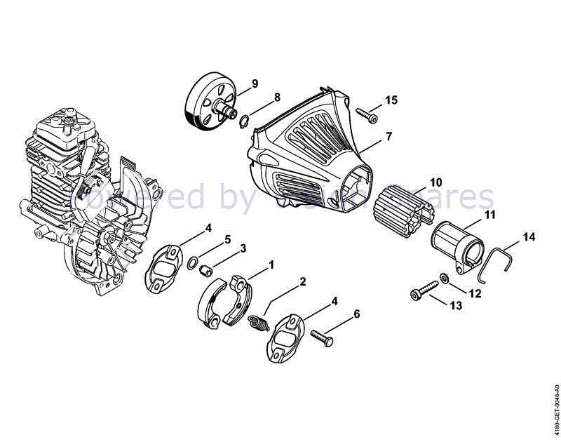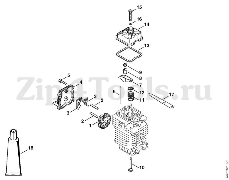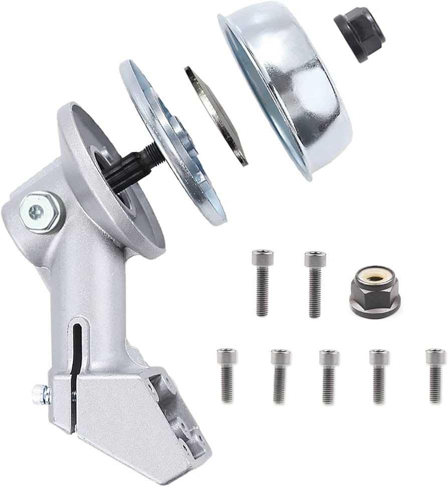
Maintaining the efficiency of any outdoor cutting tool requires a clear understanding of its key mechanical elements. By familiarizing yourself with the various components, you can ensure proper care and repair, prolonging the lifespan of the machine. Each part plays a crucial role in delivering optimal performance, whether it’s for trimming grass or handling more demanding tasks.
In this guide, we’ll explore the different sections of the machine, highlighting how they fit together to create a cohesive system. This knowledge will help you troubleshoot issues, perform routine maintenance, and identify the exact elements that might need replacement or adjustment. Keeping every piece in top condition is essential for achieving precision and reliability in your work.
Overview of the Stihl FS 111 RX Components
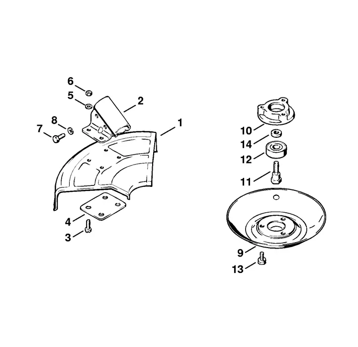
This model is equipped with a range of essential elements that work together to deliver a reliable and efficient performance. Each part plays a specific role in ensuring smooth operation, from power generation to cutting and trimming tasks. Understanding these components can help in proper maintenance and troubleshooting, allowing users to extend the lifespan and functionality of the machine.
Power Unit and Drive System
The power source of the machine is robust, providing the necessary force for demanding tasks. It is connected to the drive system, which transfers energy to the cutting tool. The drive shaft ensures that the motion is consistent and efficient, minimizing energy loss during operation.
Cutting Mechanism and Controls
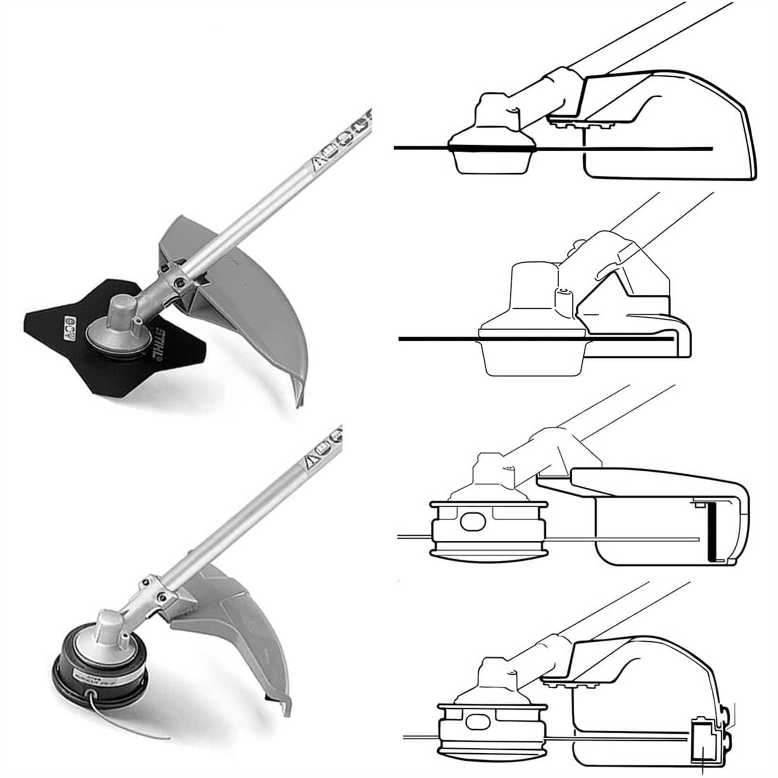
The cutting system includes a high-performance blade or string that can be easily swapped depending on the type of work. The controls are designed for easy access, allowing for precise adjustments and comfortable operation, even during extended use
Main Assembly Breakdown for Stihl FS 111 RX
The primary structure of this trimmer is composed of several interconnected components that ensure efficient performance. Understanding how each part fits together is essential for maintenance and repair. This section will highlight the key elements of the machine’s framework, providing an overview of the core units and how they interact to create a functional system.
Engine Unit and Housing
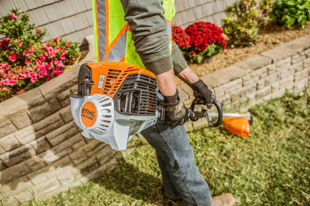
The central power source is housed within a protective casing that shields it from external damage. This area includes the motor and essential control mechanisms that drive the equipment. Proper placement and alignment of these components are crucial for smooth operation.
- Power unit casing
- Control mechanisms
- Vibration dampening system
Handle and Shaft Assembly
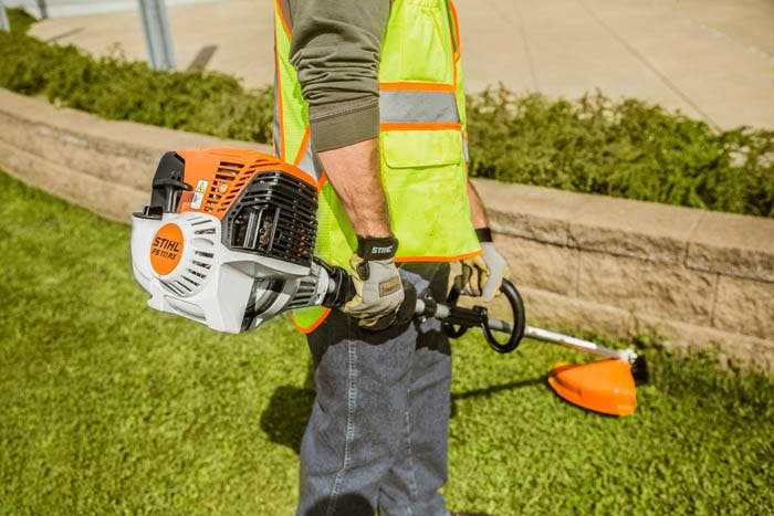
The handle and shaft form the ergonomic core, providing stability and control to the operator. These elements work together to transf
Key Engine Parts and Functions
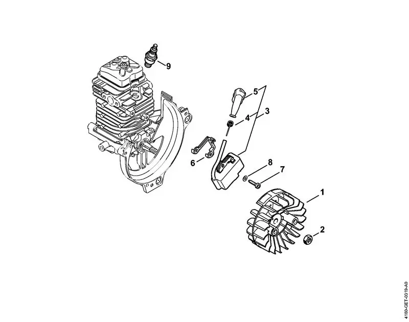
The internal mechanisms of a motor are crucial for its performance and durability. Each component works together to ensure efficient operation, and understanding their functions helps in maintaining and troubleshooting the system. Below is an overview of essential engine elements and how they contribute to the overall functionality.
| Component | Function | ||||||||
|---|---|---|---|---|---|---|---|---|---|
| Cylinder | Houses the piston and provides the space for combustion, enabling the conversion of fuel into mechanical energy. | ||||||||
| Piston | Moves within the cylinder, compressing the fuel-air mixture, which ignites to create the force needed to drive the engine. | ||||||||
| Crankshaft | Converts the linear motion of the pist
Understanding the Fuel System ConfigurationThe fuel system configuration is essential for ensuring the smooth operation of any outdoor tool powered by a combustion engine. This system is responsible for delivering the right mix of air and fuel to the engine, ensuring optimal performance under various conditions. A well-functioning setup allows the engine to operate efficiently and prevents issues like stalling or sputtering, which could result from an improper fuel mixture. At the heart of the fuel system are key components such as the carburetor Handle and Control Mechanism LayoutThe handle and control system plays a crucial role in providing the operator with full command over the machine’s performance. It ensures precision, safety, and comfort during operation by organizing the controls in an intuitive and ergonomic manner. Understanding how these elements are arranged helps users achieve optimal control in various working conditions.
|
