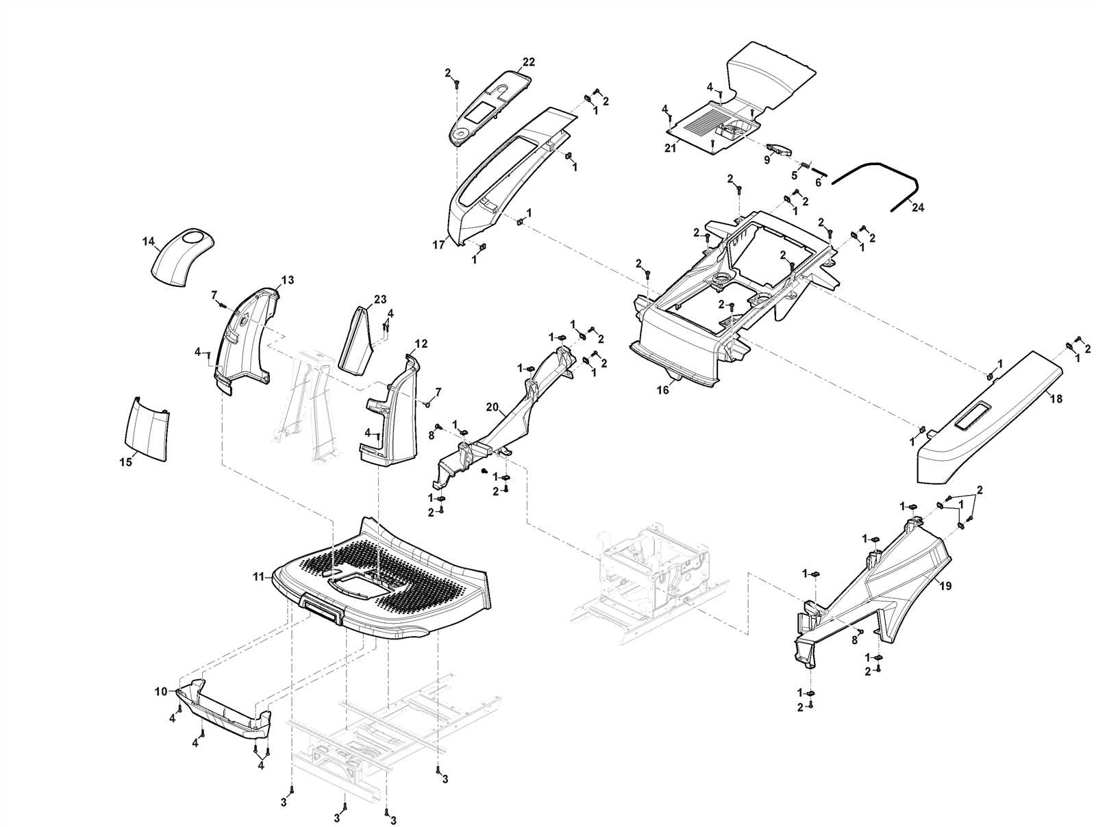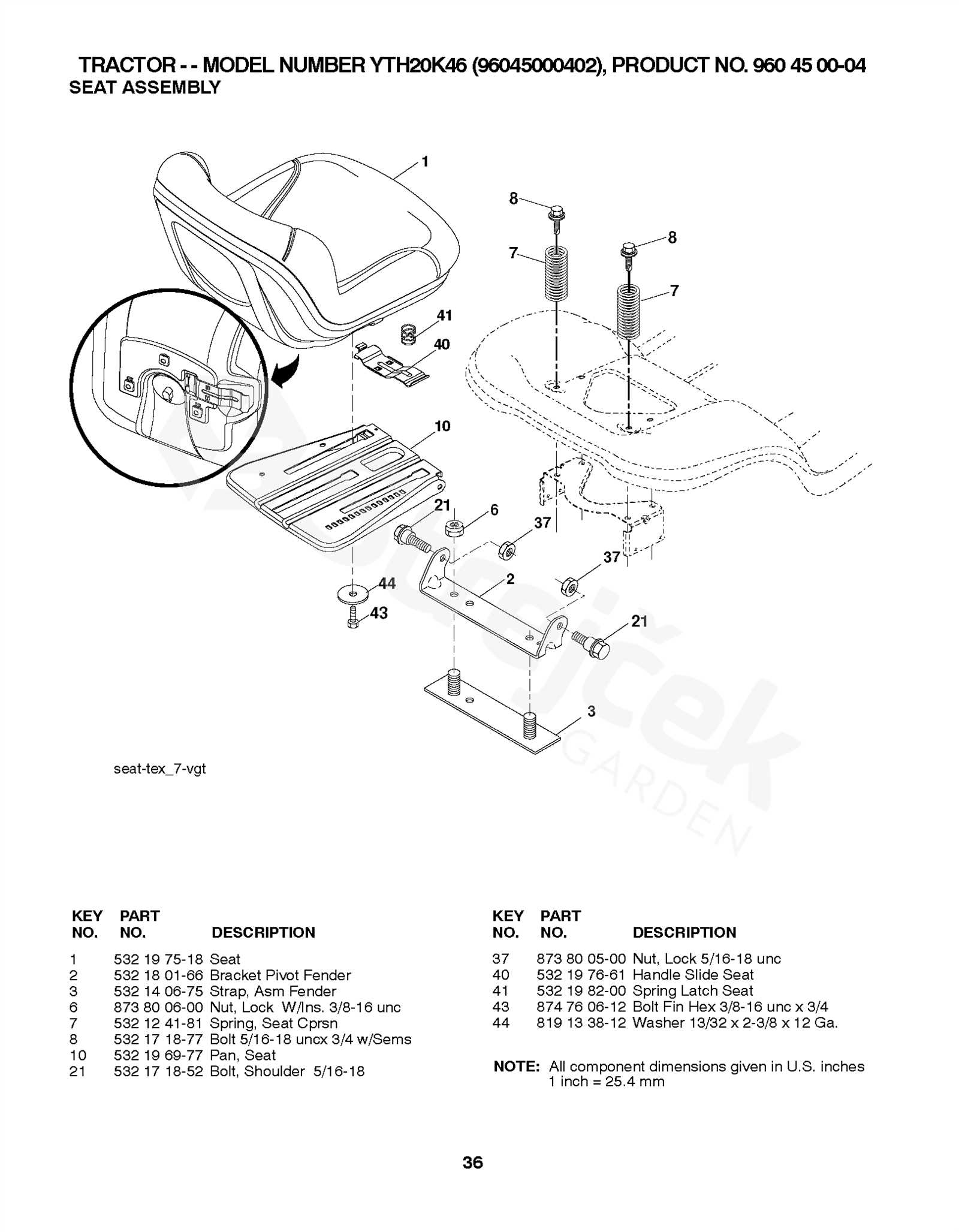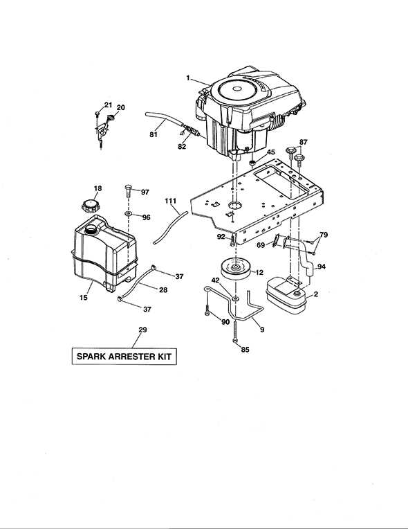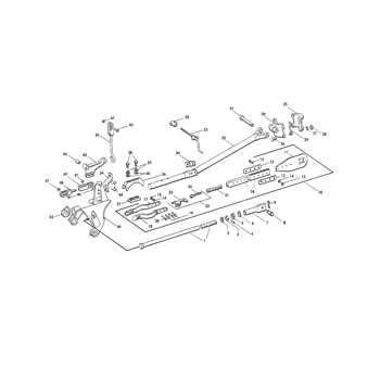
In order to maintain and service complex machinery, a clear understanding of its internal layout and how each element interacts is essential. Having a visual representation of the components helps ensure that every detail is properly accounted for during any necessary maintenance or adjustments. This overview is especially useful for those looking to identify key elements and understand their placement within the overall structure.
Exploring the detailed arrangement of various elements can assist in achieving a smoother repair process, minimizing the chances of mistakes. By familiarizing oneself with the configuration, you gain a better understanding of how everything connects and functions together. This can lead to a more efficient upkeep routine, saving both time and effort.
Moreover, understanding how each element is structured and how they are organized can be a great advantage when troubleshooting or planning upgrades. It allows one to make informed decisions about replacements and adjustments, contributing to the overall longevity and performance of the equipment.
Overview of Yth20k46 Components
This section provides a detailed look at the various elements that make up this equipment, ensuring optimal performance and reliability. Each piece has a specific role, contributing to the overall functionality and durability of the system. Understanding how these elements interact is essential for maintenance and troubleshooting.
| Component | Function | Location | ||||||||||||||||||||||||||||||||||
|---|---|---|---|---|---|---|---|---|---|---|---|---|---|---|---|---|---|---|---|---|---|---|---|---|---|---|---|---|---|---|---|---|---|---|---|---|
| Drive Assembly | Facilitates movement, ensuring smooth transitions and stability during operation. | Central base, connected to the main frame. | ||||||||||||||||||||||||||||||||||
| Cutting Deck | Responsible for trimming, designed to deliver precision and uniformity in performance. | Underneath the chassis, adjustable for varying heights. | ||||||||||||||||||||||||||||||||||
| Engine Unit | Powers the entire setup, offering the energy required for all operational tasks. | Mounted at the front, secured to the main structure. | ||||||||||||||||||||||||||||||||||
| Control Levers | Allows the operator to regulate speed and direction with ease, enhancing maneuverability. | Located on the upper panel for easy access. | ||||||||||||||||||||||||||||||||||
Steering Mechan
Understanding the Engine AssemblyThe heart of any outdoor equipment lies in its core power unit. This section provides a detailed view of how the different components work together to ensure smooth operation. It focuses on the key mechanical structures, their functions, and how they interconnect to create a reliable power source. Proper knowledge of these mechanisms is essential for maintenance and troubleshooting. The central structure is made up of various moving elements that convert energy into mechanical force. These components include intricate parts that manage air flow, fuel intake, and temperature regulation. Understanding their arrangement helps in identifying potential issues and performing necessary repairs. Additionally, the synchronization between different elements ensures efficient performance. Components like rotating shafts, cylinders, and cooling systems play crucial roles. Each element has a specific role that contributes to the overall efficiency, making the entire setup work as a cohesive unit. Exploring the Transmission System
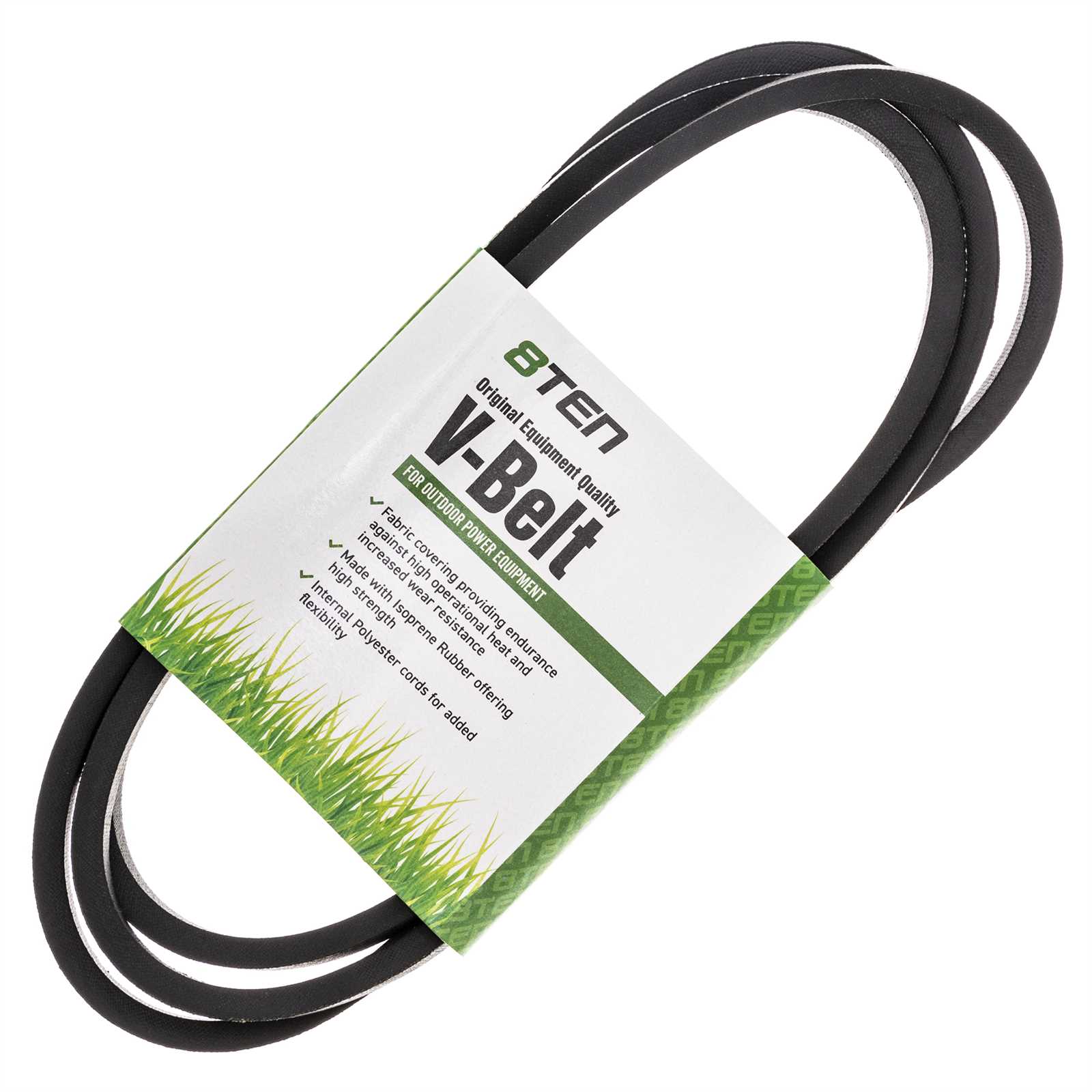
The functioning of the power transfer mechanism is crucial for efficient operation, as it governs how energy moves from the engine to the wheels. This section delves into the core elements that ensure a smooth transition of force, providing both control and speed adjustments. Understanding these components can aid in identifying potential areas for maintenance and optimizing performance. Main Components
The system consists of several interconnected parts, each playing a role in adjusting torque and speed. These components work together to adapt to different terrains and conditions, ensuring that power is appropriately distributed. Below is an overview of the key elements:
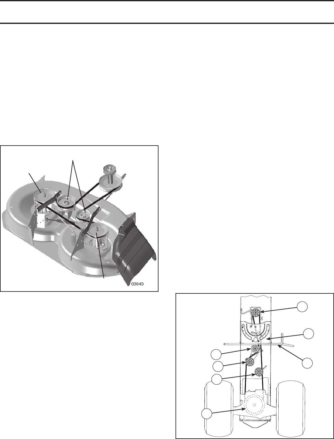
Maintenance TipsRegular inspection of the power transfer mechanism can prolong its lifespan and prevent unexpected breakdowns. Key areas to monitor include fluid levels, belt tension, and the condition of the gears. Timely replacement of worn components can maintain optimal performance and prevent more costly repairs in the future. Blade Deck Structure and FunctionThe lower assembly, crucial for effective grass management, is designed to achieve consistent cutting results across various terrains. This segment combines multiple mechanical elements to provide durability and precision, contributing to overall lawn quality. Each part of this system is engineered to work in harmony, ensuring smooth performance and ease of maintenance. Key Components OverviewUnderstanding the primary elements of this lower platform helps in recognizing how each part contributes to a smooth and efficient operation. Below is a summary of the main structural pieces and their functions:
Durability and Maintenance
The construction of this assembly ensures longevity, with materials chosen for resistance to wear and environmental conditions. Regular upkeep, such as lubrication and sharpening, extends its lifespan and maintains cutting effici Examining the Steering MechanismThe system that allows precise navigation and directional control is crucial for ensuring smooth movement and responsiveness. It is composed of interconnected components that work together to translate user input into accurate changes in direction. This section explores the primary elements involved, focusing on how they collaborate to maintain stability and control. Key Components and Their RoleThe setup involves a series of linked arms, joints, and rods that translate the rotation of the wheel into precise movement. Each piece is designed to pivot or rotate, ensuring that directional commands are transmitted smoothly. A central rod acts as the main link between the input control and the mechanical arms, ensuring that changes in direction are transferred with minimal delay. Maintaining Stability and ControlEffective control relies on the proper alignment and condition of the moving parts. Regular adjustments and inspections are necessary to ensure that all elements move fluidly without resistance. Proper lubrication of the joints reduces friction, contributing to smoother performance and extending the lifespan of the mechanism. Detailed View of Electrical System
The electrical framework of this machinery plays a critical role in its overall functionality and performance. Understanding the layout and components involved is essential for effective maintenance and troubleshooting. This section delves into the intricate arrangement of the system, highlighting the connections and relationships between various elements. At the core of the system lies the power distribution unit, responsible for managing electrical flow to all operational components. This unit ensures that each part receives the appropriate voltage and current levels, promoting optimal performance. Alongside this, the control module serves as the brain, coordinating the interactions between different systems to guarantee smooth operation. Additionally, wiring harnesses are integral to the setup, providing the necessary pathways for electrical signals. These harnesses are designed to withstand environmental stresses, ensuring longevity and reliability. In conjunction with fuses and relays, the entire system is safeguarded against overloads and short circuits, enhancing safety during operation. Regular inspection and maintenance of the electrical components are vital for preventing failures. By staying informed about the configuration and functioning of each part, operators can effectively troubleshoot issues and ensure the machinery remains in peak condition. Brake System BreakdownThe braking mechanism is a crucial component of any machinery, ensuring safety and control during operation. Understanding the layout and function of each element within this system is essential for effective maintenance and troubleshooting. This section delves into the various components that make up the braking system, highlighting their roles and interconnections. Each part plays a vital role in the overall functionality, contributing to the efficiency and reliability of the system. Below is a detailed overview of the main elements involved in the braking mechanism:
By familiarizing oneself with these key components, operators can better appreciate the intricacies of the braking mechanism and ensure its optimal performance. Fuel System AnalysisThe performance and efficiency of any engine heavily depend on the proper functioning of its fuel delivery mechanism. A comprehensive examination of this system reveals how fuel is stored, transported, and injected into the combustion chamber. Understanding these components is essential for diagnosing issues and ensuring optimal operation. Key components of the fuel delivery mechanism include:
A systematic approach to evaluating the fuel delivery mechanism involves several steps:
Regular maintenance and analysis of the fuel delivery system can prevent performance issues, improve fuel efficiency, and extend the engine’s lifespan. Proper understanding of these components and their functions is vital for effective troubleshooting and optimization of engine performance. Troubleshooting Common Part Issues
When dealing with mechanical components, various challenges may arise, affecting performance and efficiency. Identifying and resolving these issues promptly is crucial for maintaining optimal functionality. Below are common problems encountered and suggestions for addressing them.
By addressing these common concerns, you can significantly enhance the reliability and lifespan of the equipment. Regular maintenance checks and following manufacturer guidelines will aid in early detection and resolution of potential problems. |
