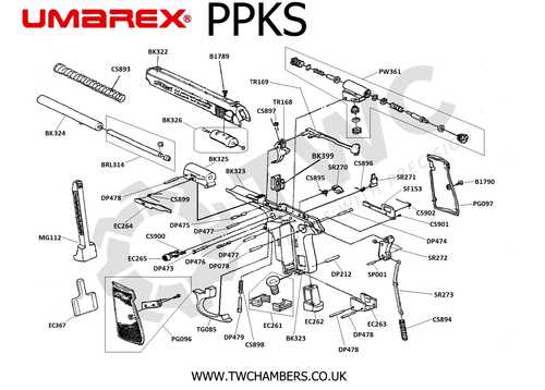
Understanding the intricate arrangement of various elements in mechanical and air-powered devices is essential for ensuring optimal performance and maintenance. These detailed blueprints offer a clear perspective on how different mechanisms work together, providing a reliable guide for repairs and adjustments.
In these visual layouts, you’ll find a structured breakdown of essential components, showing their positioning and interaction. This type of layout helps to pinpoint specific areas that may require attention, enabling users to effectively manage upkeep and troubleshoot potential issues.
Whether you’re a beginner or experienced in handling such devices, having access to these detailed schematics simplifies the process of identifying and working with individual elements. They serve as a valuable tool for anyone looking to maintain or modify their equipment.
Understanding Umarex Parts Diagrams
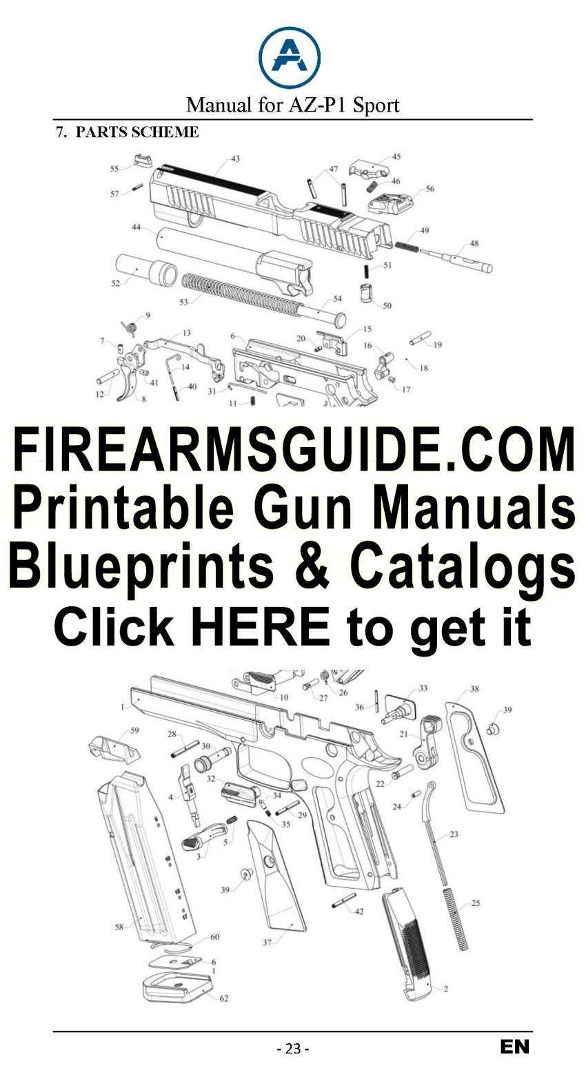
Technical blueprints serve as an essential tool for comprehending how various components interact within a mechanical system. These visual aids allow users to explore intricate details, offering a comprehensive breakdown of each element’s role and placement within the overall structure.
Through careful examination, one can gain insights into the inner workings of the device, identify individual sections, and understand their relationship to one another. This process helps to enhance both maintenance and repair efforts, ensuring a smooth operational experience by facilitating the identification of specific elements that may require attention.
How to Interpret Airgun Schematics
Understanding airgun schematics is essential for anyone looking to maintain or repair their equipment effectively. These technical drawings represent the internal structure and mechanisms of airguns, showing how each element connects and functions. Mastering the ability to read and analyze such drawings can significantly improve your ability to troubleshoot and enhance performance.
When examining a schematic, it’s important to break down the image into recognizable sections. Each component is usually labeled with numbers or codes that correspond to a list of parts and their descriptions. By following this approach, you can easily identify the relationships between the elements and gain a deeper understanding of how the system operates as a whole.
- Symbols: Schematics use specific symbols to represent mechanical parts like springs, valves, and pins. Learn to recognize these icons to interpret the drawing correctly.
- Flow of Action: Pay attention to how components interact with each other in sequence. Arrows or lines often indicate
Common Components Found in Umarex Diagrams
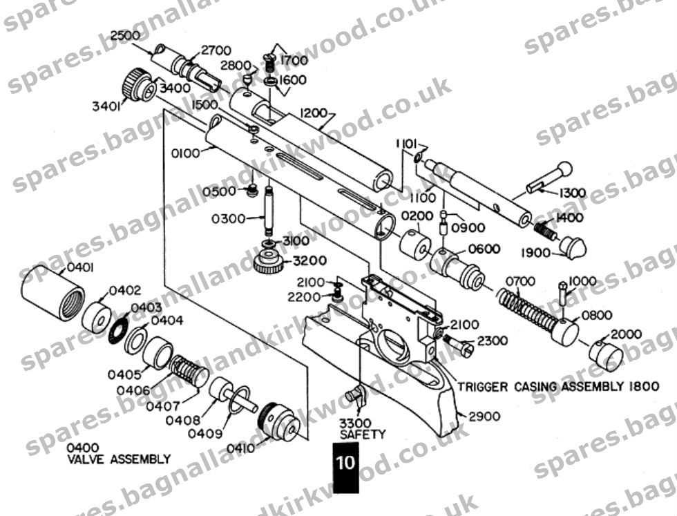
Many illustrations of mechanical setups showcase a variety of key elements that play crucial roles in ensuring proper functionality. These elements are often central to maintaining the overall structure and performance of the system. Understanding these components is essential for anyone interested in repairs, modifications, or general maintenance.
- Barrel Assembly – The main tube responsible for directing projectiles, often consisting of multiple interconnected parts for stability and precision.
- Trigger Mechanism – A complex set of levers and springs designed to release the firing mechanism when activated.
- Seals and O-rings – Vital for preventing gas or air leakage, ensuring the system remains pressurized and operates efficiently.
- Valve System – Controls the flow of gas or air, regulating the release necessary for operation.
- Stock – The rear part providing support and comfort to the user, usually designed to
Benefits of Using Parts Diagrams for Repairs
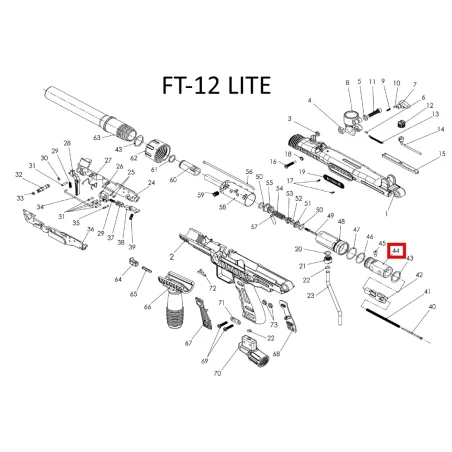
Visual guides play a crucial role in simplifying the maintenance and restoration of various devices. They offer a clear representation of components and their arrangement, which helps users quickly understand the structure of the system and identify the necessary elements for replacement or adjustment. This leads to more efficient and accurate repair work, reducing the risk of mistakes.
Improved Efficiency in Repairs
When following visual guides, individuals can easily pinpoint the areas that require attention. This eliminates guesswork and significantly speeds up the process. By having a detailed illustration of how everything fits together, repairs are carried out with greater precision, minimizing trial and error.
Cost-Effective Maintenance
Another significant advantage is the ability to perform repairs independently without relying on professional services. By understanding the layout and connections between various elements, individuals can confidently tackle even complex fixes. This reduces the overall cost of maintenance, as fewer external services are needed.
Advantage Description Time-Saving Quick identification of elements ensures faster repairs. Where to Find Airgun Schematics
Understanding the internal components and how they work together is essential for maintaining or repairing any airgun. Access to detailed visual guides can make this task significantly easier, allowing users to quickly identify specific mechanisms and their correct placement.
There are several reliable resources online where you can find comprehensive visual guides for air-powered models. These resources typically offer exploded views and labeling of each component, providing a clear insight into the inner workings of the device.
- Manufacturer websites often offer downloadable schematics and maintenance guides for various models.
- Online forums and hobbyist communities frequently share detailed visual references contributed by enthusiasts.
- Retailers that specialize in air-powered gear sometimes include guides as part of their product descriptions.
Having access to these detailed illustrations helps owners maintain their airguns in top condition and facilitates any necessary repairs or part replacements
Key Symbols Used in Umarex Schematics
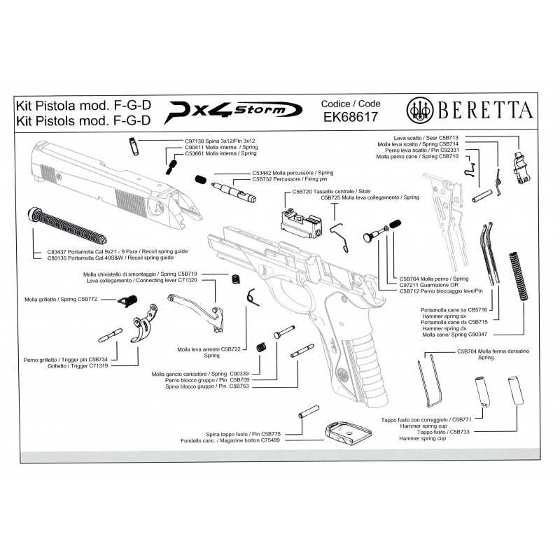
Understanding the symbols employed in technical illustrations is essential for effective navigation and interpretation of complex designs. These graphical representations serve as a universal language, allowing users to grasp the essential components and their interrelationships within the assembly. A clear comprehension of these symbols aids in troubleshooting, maintenance, and assembly processes.
Among the most common symbols found in technical illustrations are those representing electrical components, such as resistors, capacitors, and switches. Each symbol is designed to convey specific information quickly and efficiently, ensuring that users can identify the function of each element without ambiguity. Additionally, symbols denoting mechanical parts, such as gears, bearings, and fasteners, are standardized to facilitate a universal understanding across different platforms.
Another critical aspect is the use of arrows and lines, which indicate the direction of flow, movement, or connection between various components. These directional indicators are vital for comprehending the operational mechanics of the system being illustrated. Furthermore, annotations often accompany symbols to provide additional context, such as specifications, tolerances, or material types, enhancing the clarity of the technical representation.
By familiarizing oneself with these essential symbols and their meanings, users can enhance their ability to work with complex assemblies. This knowledge not only streamlines the process of assembly and repair but also fosters a deeper understanding of the underlying mechanics at play.
Differences Between Exploded Views and Schematics
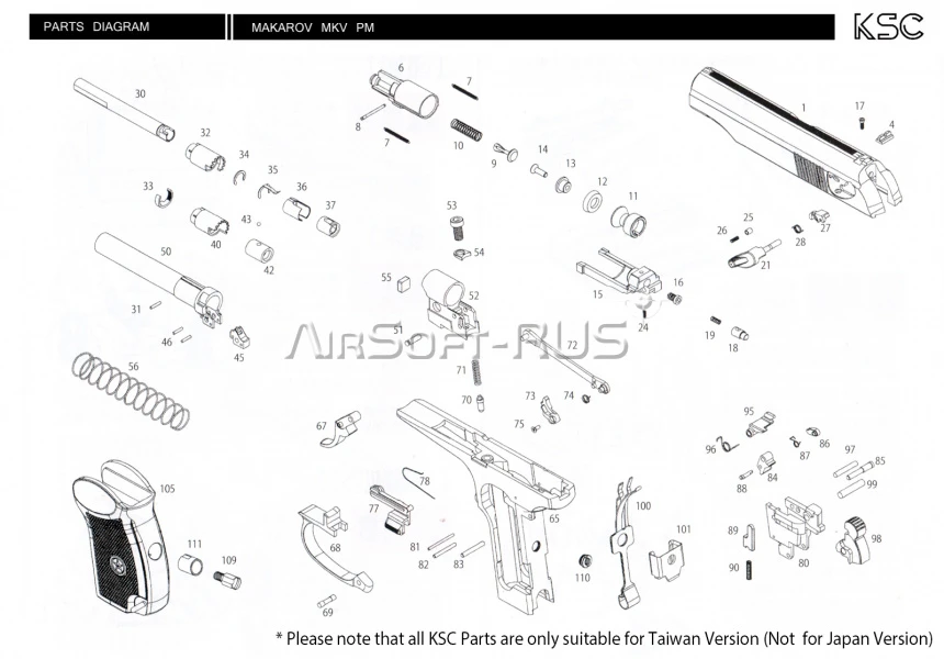
Understanding the distinction between two common visual representations is essential for accurate interpretation and effective assembly. Each type of illustration serves a unique purpose, catering to specific needs in the realm of mechanical design and analysis. The clarity with which these images convey information can greatly influence the efficiency of repairs and modifications.
Purpose and Use
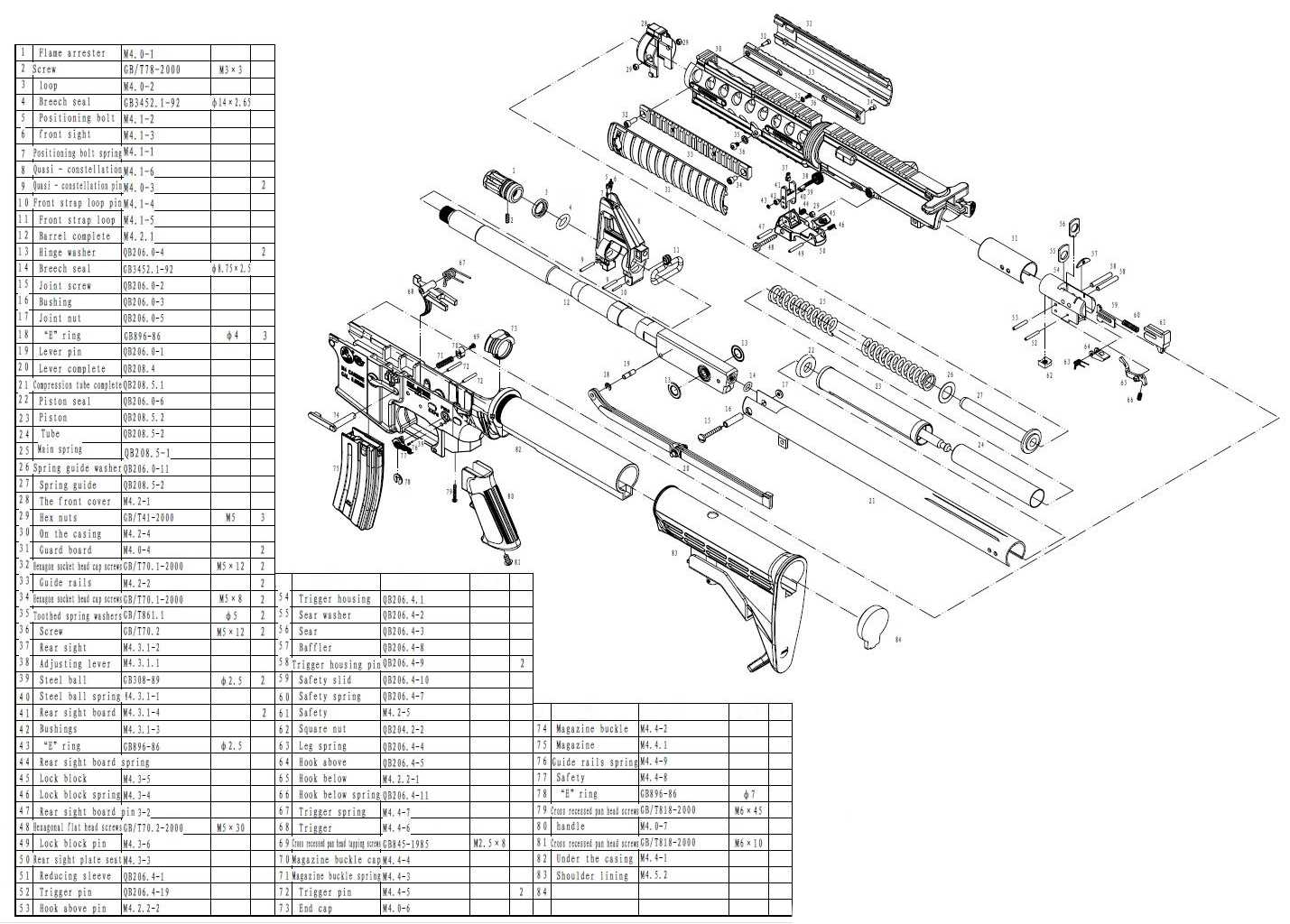
Exploded views and schematics are both valuable tools, but they differ fundamentally in their objectives. Exploded views are designed to showcase the components of an assembly in a way that emphasizes their arrangement and relationship to one another. Conversely, schematics focus on the functional aspects of the system, illustrating how various elements interact to create a cohesive operation.
Visual Representation
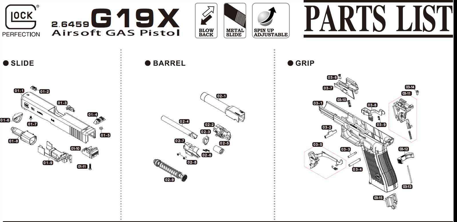
The format and presentation of these illustrations further highlight their differences. Exploded views typically depict three-dimensional renderings, where components are separated along an axis to clarify how they fit together. Schematics, on the other hand, are often two-dimensional and utilize symbols and lines to represent connections and workflows, prioritizing the logical flow over physical placement.
Feature Exploded Views Schematics Objective Show arrangement of components Illustrate functional relationships Dimension Three-dimensional Two-dimensional Representation Style Separated components Symbols and lines Usage Assembly and disassembly guidance Troubleshooting and operational understanding Troubleshooting with Umarex Parts Diagrams
When faced with issues in your equipment, a visual reference can be invaluable for effective resolution. Utilizing detailed schematics allows users to pinpoint the source of problems, facilitating a smoother repair process. Understanding the layout and components of your device is crucial for addressing any malfunctions efficiently.
To begin the troubleshooting process, identify the symptoms of the malfunction. This may include inconsistent performance, unusual sounds, or failure to operate. Once the symptoms are noted, consult the corresponding illustrations to locate the relevant sections of the equipment. By cross-referencing these visuals with the observed issues, users can gain insights into which components may require inspection or replacement.
For instance, if the device exhibits a loss of power, check the power source and connections. The visual reference will help in identifying the relevant parts involved in the power supply chain. Additionally, consider examining any safety mechanisms or switches that might be affecting functionality.
Furthermore, when replacing any faulty elements, ensure that the new components are compatible with your specific model. The schematics often include part numbers and descriptions, making it easier to procure the right replacements. Following this systematic approach not only simplifies the repair process but also enhances the longevity and performance of your device.
In conclusion, having access to visual guides is essential for effective troubleshooting. By leveraging these resources, users can methodically identify and resolve issues, ensuring their equipment remains in optimal working condition.
Tips for Ordering Spare Parts from Diagrams
When it comes to acquiring replacement components for your equipment, understanding how to effectively utilize visual schematics can significantly streamline the process. Having a clear approach to sourcing these essential items ensures that you receive the correct pieces promptly, minimizing downtime and maintaining the functionality of your machinery.
1. Identify the Required Components
Before placing an order, carefully examine the visual representation to pinpoint the specific components you need. Take note of any part numbers or identifying features that can aid in ensuring accuracy. This initial step can prevent mistakes and facilitate a smoother transaction.
2. Choose a Reliable Supplier
Once you have identified the necessary items, it is crucial to select a trustworthy source for your purchase. Look for vendors who specialize in the type of components you are seeking. Reading customer reviews and verifying the reputation of the supplier can greatly enhance your confidence in the purchasing process.