The performance and longevity of outdoor equipment heavily rely on the proper arrangement and understanding of its internal structure. When working with such machines, knowing how the various elements fit together is essential for both maintenance and troubleshooting. This section focuses on detailing the layout and key elements, offering insights into how the different components interact to deliver optimum results.
Understanding the overall structure can greatly enhance efficiency when performing routine check-ups or repairs. By having a clear map of each functional element, users can easily identify any areas that may need attention, ensuring smooth operation. This guide provides a detailed look at the most vital areas of the system, helping you maintain it in peak condition.
Each section of the layout plays a specific role, contributing to the machine’s performance. Whether it’s about upkeep or improving functionality, having a clear grasp of the internal configuration ensures better handling and care. With the right knowledge, you can prevent potential issues before they arise, prolonging the life of the equipment.
Scag Turf Tiger 61 Component Overview

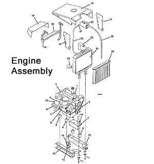
The machine at hand is designed with efficiency and durability in mind, making it a top choice for managing extensive landscapes. This model is equipped with a robust set of elements that ensure long-lasting performance and ease of maintenance. Its components are carefully engineered to handle a wide variety of tasks, providing reliability under heavy usage and ensuring smooth operations.
Engine and Power System
The heart of this machine is its high-powered engine, designed to deliver consistent and strong output. This core feature is complemented by an advanced fuel system that optimizes consumption, allowing for extended operation without frequent refueling. With a focus on reducing emissions and increasing energy efficiency, the power system stands as a crucial part of the overall design.
Cutting Mechanism

The cutting mechanism is engineered for precision and efficiency. It features a reinforced blade assembly that maintains sharp
Understanding the Drive System Layout
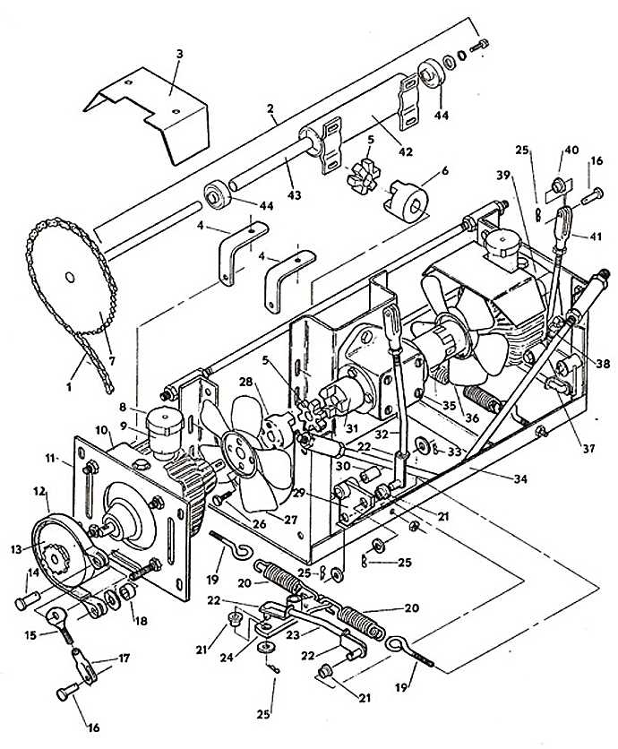
The structure of the propulsion system in a high-performance mower is crucial for smooth operation and durability. By exploring how the various components interact, you can gain insight into the system’s overall functionality and maintenance needs. This section will help you familiarize yourself with the key aspects of the power transmission layout.
Main Components Overview
At the core of the drive system is a series of mechanical elements designed to convert energy from the engine into the movement of the machine. These components typically include hydraulic pumps, motors, and the assembly of linkages that ensure precise control of speed and direction. Understanding how these parts work together allows for efficient performance and helps in troubleshooting potential issues.
Hydraulic Flow and Control
The hydraulic system plays a pivotal role in controlling the flow of power throughout the machine. Fluid movement from the
Key Elements of the Cutting Deck
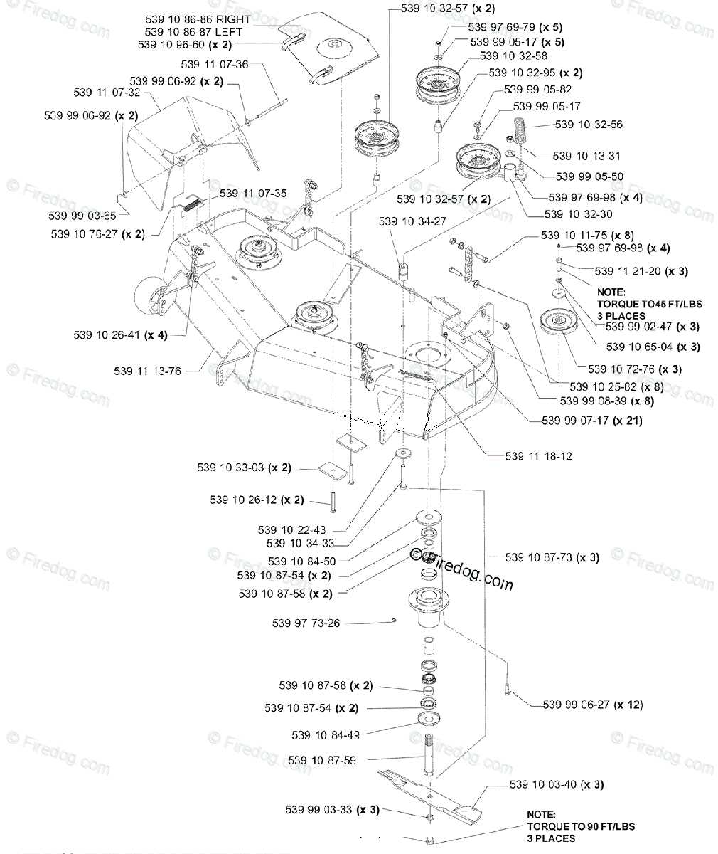
The cutting mechanism is a vital component responsible for ensuring precise and efficient grass trimming. Its structure comprises various interconnected parts, all contributing to smooth operation and optimal performance. This section focuses on the primary features that facilitate seamless operation and a clean cut.
| Component | Description | ||||||||||||
|---|---|---|---|---|---|---|---|---|---|---|---|---|---|
| Blades | Sharp rotating elements that slice through the grass, ensuring even trimming across the lawn. | ||||||||||||
| Spindles | Mechanical supports that connect the blades to the deck, ensuring they spin at the required speed for efficient cutting. | ||||||||||||
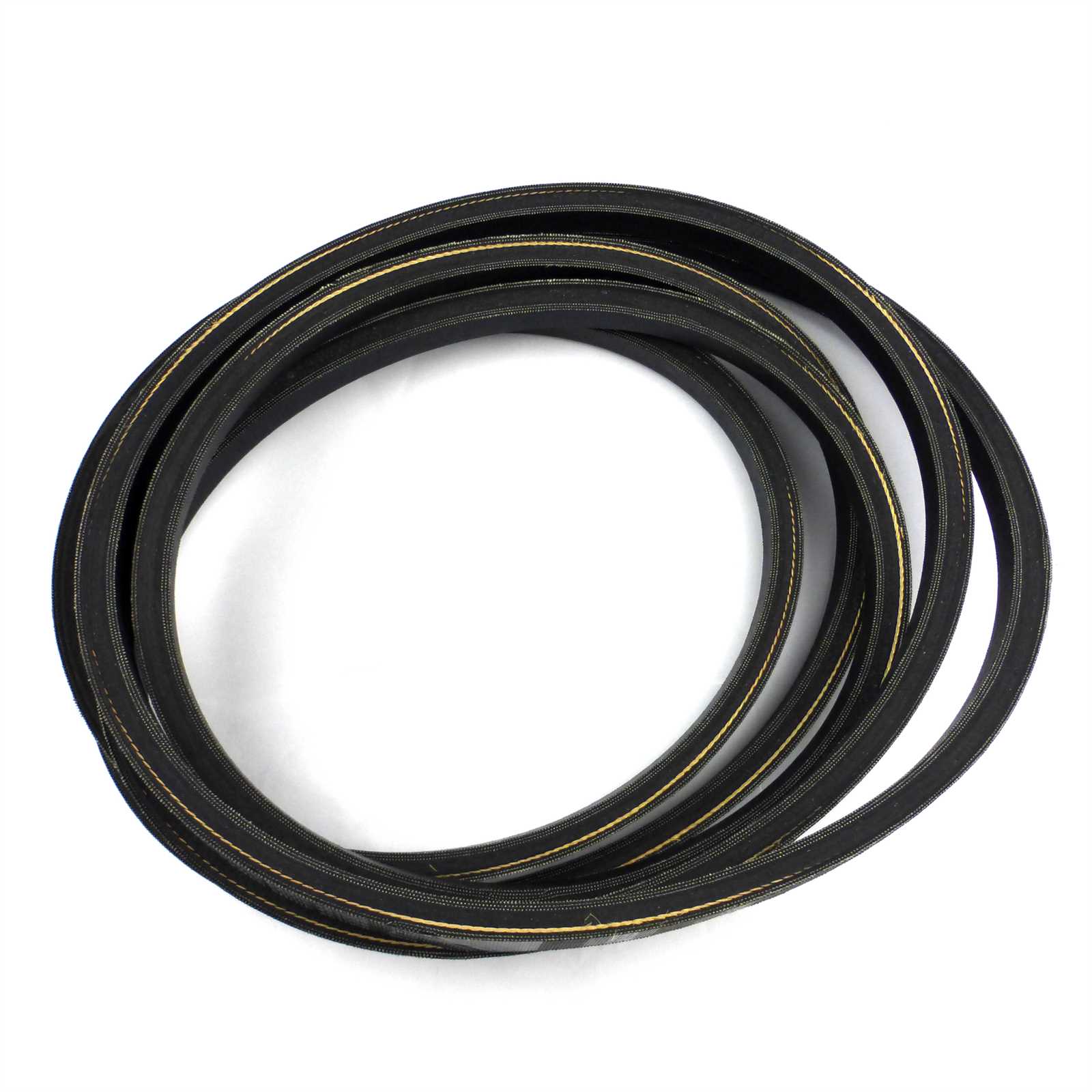
| Belt System | A set of belts that transfer power from the engine to the blades, enabling smooth rotation and cutting. | ||||||||||||
| Deck Shell | The main body that houses the cutting components
Hydraulic System Structure and Functionality
The hydraulic system is an integral component of many modern machines, allowing them to perform tasks that require significant power and precision. By utilizing fluid pressure, this system provides smooth and efficient control over various mechanical functions. Understanding how its components interact is key to optimizing performance and maintenance.
Through the combination of these key elements, the hydraulic system ensures reliable functionality, adapting to different operational demands while maintaining consistent performance. Blade Assembly and Maintenance TipsKeeping the cutting components in optimal condition is essential for consistent and precise performance. Proper assembly and regular upkeep not only improve efficiency but also extend the lifespan of your equipment. In this section, we will explore essential advice to ensure safe installation and long-lasting durability of these critical parts. Correct Blade InstallationBefore starting any work, ensure all safety precautions are followed. Align the sharp edges in the correct orientation for effective operation. Tighten the fastening elements securely, but avoid overtightening, as it may cause unnecessary stress or wear on the components. Always double-check the installation to ensure smooth operation. Maintenance for Optimal PerformanceRegular inspections help to identify signs of wear, such as dull edges or deformities. Sharpening the cutting surfaces periodically will maintain high cutting efficiency, while replacing them when necessary prevents further damage. Additionally, ensure the balance is maintained after sharpening to avoid vibrations during use, which can lead to further issues. Exploring the Electrical Connections and WiringUnderstanding the electrical layout in a machine is essential for ensuring smooth operation and quick troubleshooting when issues arise. The electrical system comprises various components that require precise coordination to maintain functionality. Proper knowledge of how different elements are connected can help prevent malfunctions and extend the lifespan of the machine. The network of wires within the system links several critical elements, from power sources to control mechanisms. This web of connections ensures that each component receives the necessary signals and power to function optimally. Below is a breakdown of key sections that are connected via the wiring system.
|

