| Cooling Mechanism Breakdown and Function
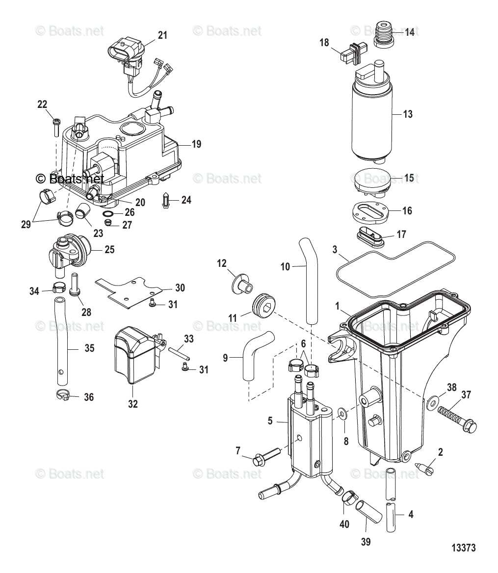
The cooling system plays a vital role in ensuring the efficient operation and longevity of the engine. This system prevents excessive heat buildup during operation by channeling thermal energy away from critical components. Understanding how it functions can provide insights into maintaining optimal performance and reducing wear.
Main Components of the System
The key elements involved in the process include the circulation of fluid, thermostats, and conduits that direct the cooling medium. Each part contributes to regulating the engine’s temperature by ensuring that heat is dissipated in a controlled and efficient manner. The fluid flow is critical in transporting heat from high-temperature areas to a designated outlet.
Flow and Regulation Process
As the engine operates, the coolant circulates through a network of channels, absorbing heat from various zones. Thermostats monitor the temperature, adjusting the flow as needed to maintain an optimal range. This cyclical process helps in avoiding
Electrical System and Wiring Configuration
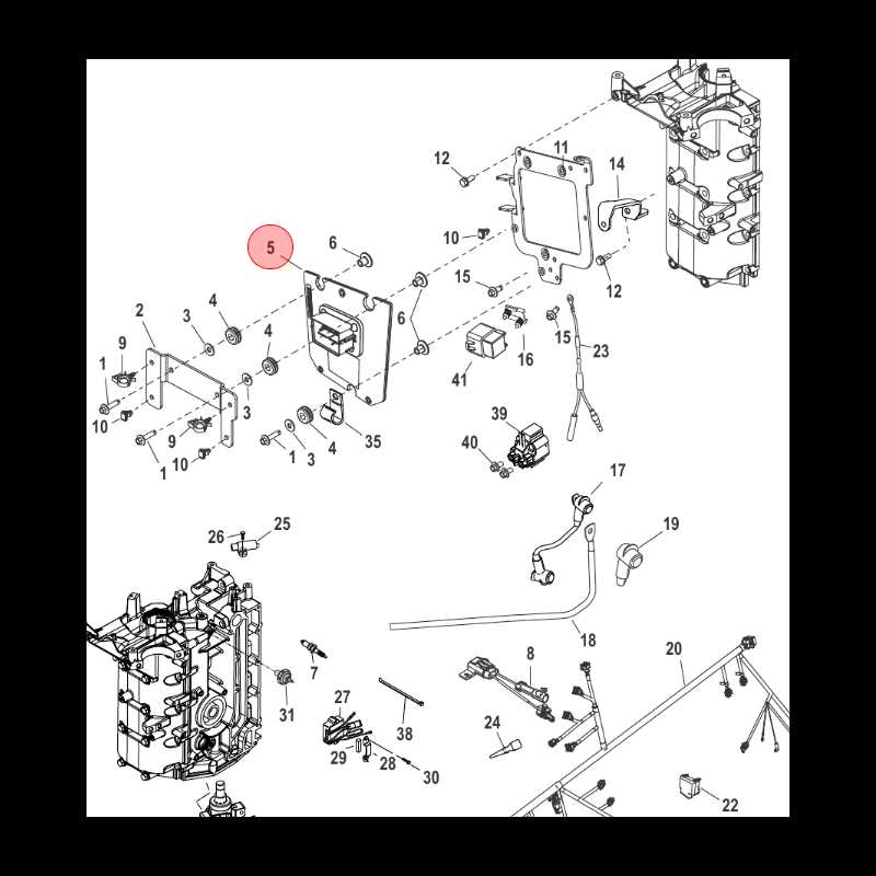
The electrical setup is a critical component for ensuring efficient and safe operation. Understanding the layout of connections and how they interact with various elements is essential for maintaining peak performance. A well-organized configuration not only supports smooth functioning but also simplifies troubleshooting when issues arise.
Key Components: The system typically involves various essential elements like the ignition switch, alternator, and battery. These elements work together to provide the necessary energy and control to power multiple devices onboard.
Wiring Essentials: Each wire plays a vital role in the distribution of electrical power across different areas. Proper insulation and secure connections are necessary to avoid malfunctions and ensure consistent power flow throughout the entire configuration.
Gearbox and Propulsion Components

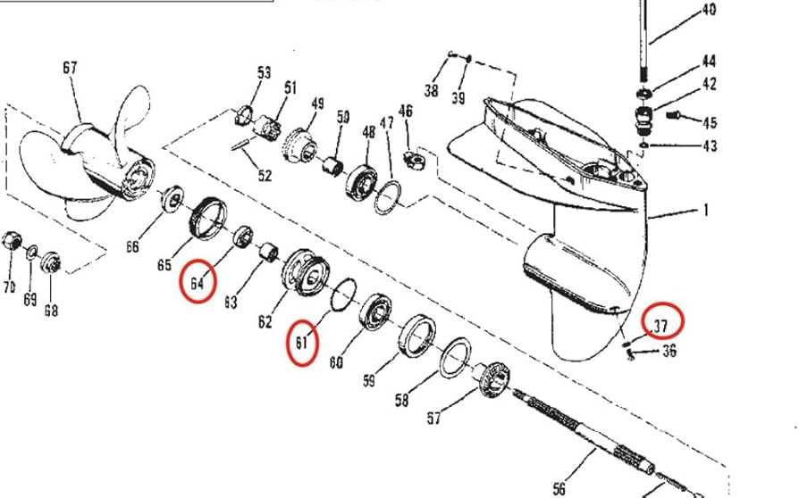
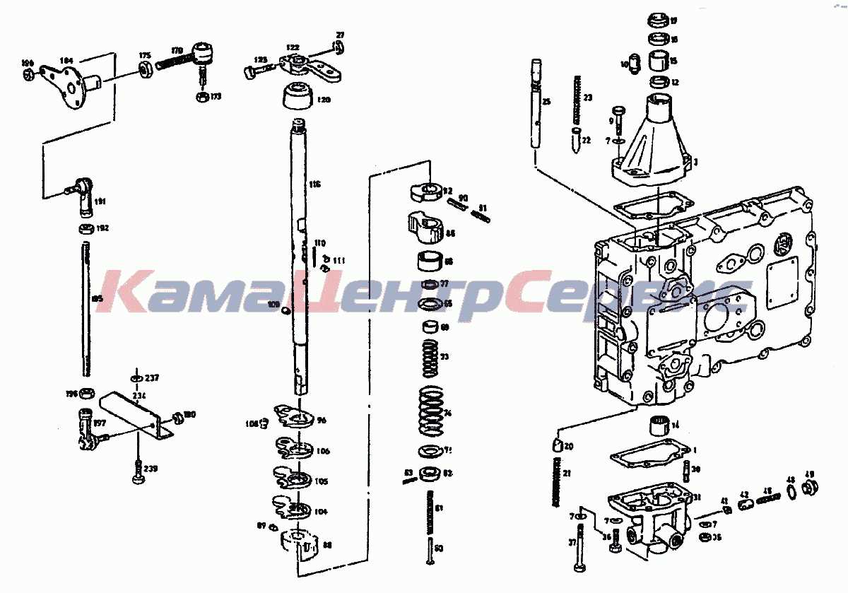
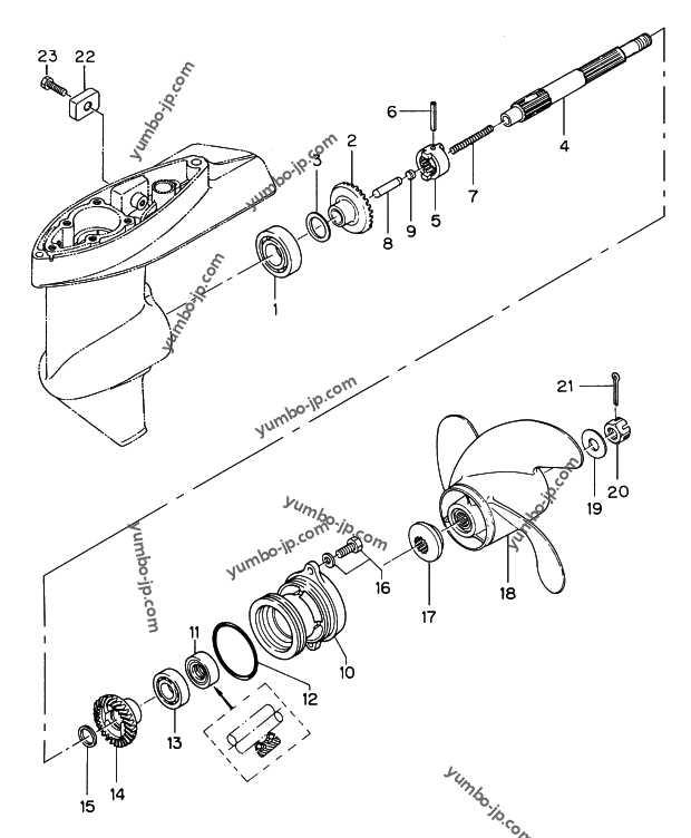
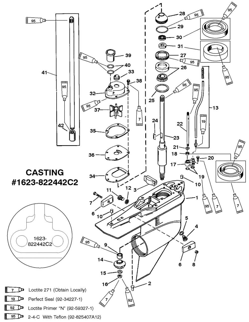
The gearbox and propulsion elements play a crucial role in ensuring efficient movement and control of marine vessels. These systems convert engine power into thrust, enabling the boat to maneuver effectively through water. Understanding the intricacies of these components can enhance performance and reliability during operation.
At the heart of the propulsion system is the gearbox, which facilitates the transfer of power from the engine to the propeller. This assembly typically includes various gears that adjust the torque and speed, optimizing performance based on the vessel’s requirements. Additionally, the alignment of the gearbox with the engine is vital for minimizing wear and ensuring smooth operation.
The propeller, an essential part of the propulsion mechanism, translates rotational energy into forward motion. Different designs and pitches of propellers can significantly impact efficiency and speed. Selecting the appropriate propeller type involves considering factors such as vessel size, weight, and intended use, which directly affect overall performance.
Moreover, the connection between the gearbox and propeller shaft is critical for effective power transmission. Proper maintenance of seals and bearings in this area ensures longevity and reduces the risk of failure. Regular inspection and servicing can prevent issues that may arise from wear and tear, enhancing the vessel’s operational reliability.
Throttle and Control System Elements
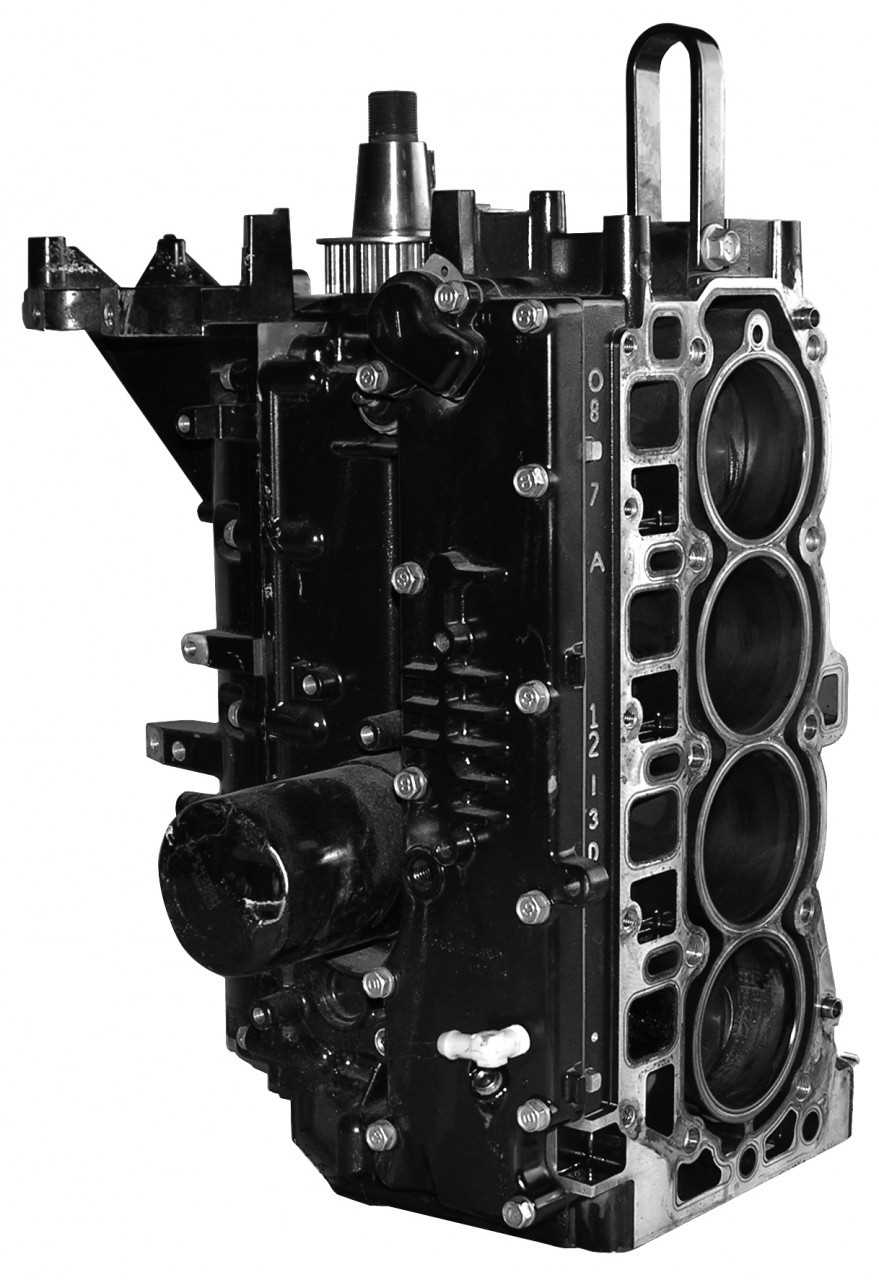
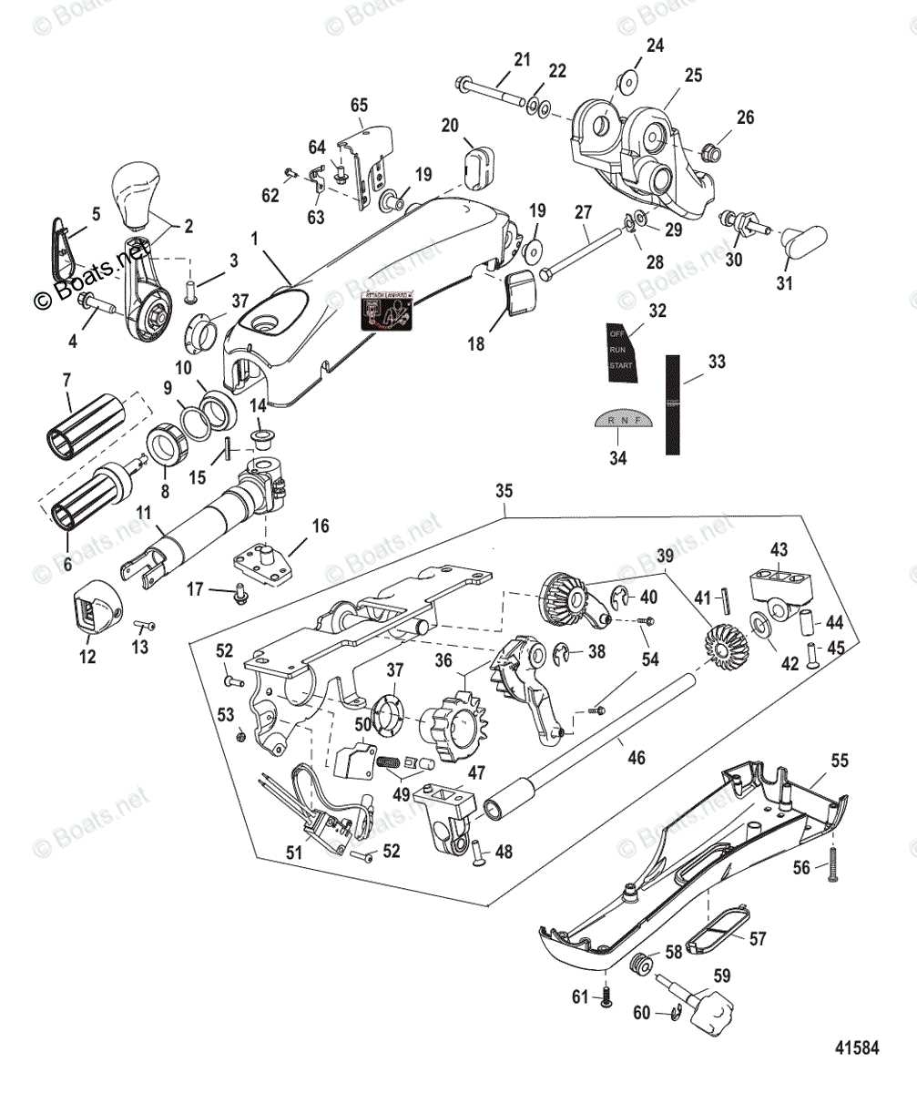
The throttle and control system play a pivotal role in managing the performance and responsiveness of marine engines. These components work in harmony to regulate the flow of fuel and air, ensuring optimal operation during various boating activities. A well-designed control system enhances user experience by providing smooth transitions and precise handling.
Central to this assembly is the throttle lever, which allows the operator to adjust engine speed seamlessly. Connected to the lever is the cable assembly, responsible for transmitting the user’s input to the engine’s throttle body. Additionally, the control box houses crucial mechanisms for shifting gears, integrating functionalities that facilitate effortless navigation.
The linkage system serves as the backbone, connecting all elements and ensuring synchronized movement. Regular maintenance of these components is essential for optimal performance. Understanding the various elements of the control system enables boaters to diagnose issues efficiently and maintain their vessels in peak condition.
Exhaust System Design and Flow
The design and functionality of an exhaust system play a crucial role in optimizing engine performance and efficiency. By facilitating the expulsion of combustion gases, a well-engineered exhaust setup enhances power output while minimizing harmful emissions. Understanding the dynamics of gas flow within this system is essential for maintaining effective engine operation and longevity.
Key Components of Exhaust Flow
Several vital elements contribute to the overall efficiency of exhaust gas flow. Pipes must be constructed to minimize resistance, ensuring smooth passage of gases. Headers are critical in directing exhaust away from the engine and can significantly influence backpressure levels, which in turn affects engine responsiveness. The use of mufflers not only serves to reduce noise but also impacts flow characteristics by allowing gases to expand and exit efficiently.
Impact of Design on Performance
The geometry of the exhaust system directly affects performance outcomes. A system with optimized bends and smooth transitions minimizes turbulence, allowing for a more effective flow of exhaust gases. Additionally, the diameter of the pipes should be carefully selected; larger diameters may reduce backpressure but could sacrifice low-end torque, while smaller diameters can enhance throttle response. Balancing these factors is essential for achieving desired performance metrics.
Lubrication Pathways and Maintenance
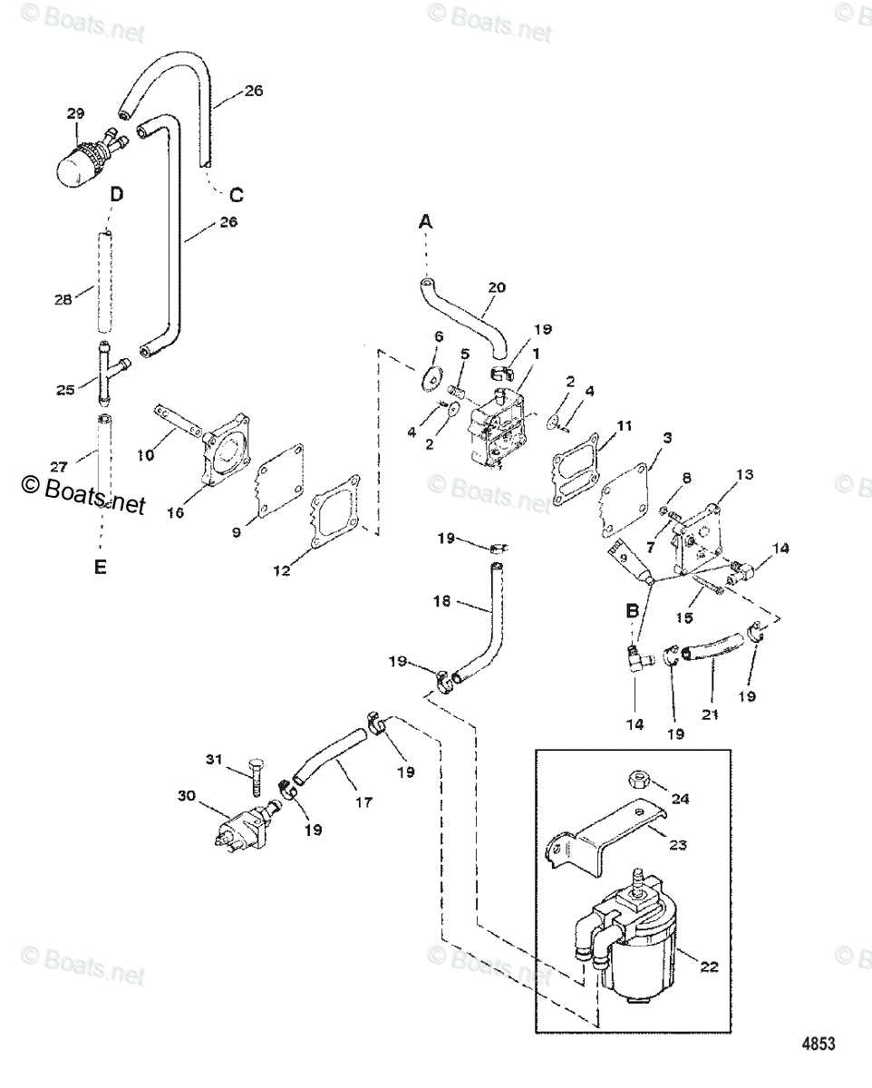
Efficient operation of marine engines relies heavily on proper lubrication systems that ensure all moving components receive adequate protection. Understanding how lubricants flow through the system not only aids in enhancing performance but also extends the lifespan of the machinery. Regular upkeep of these pathways is essential to prevent wear and tear, ensuring that the engine functions smoothly under various conditions.
Understanding Lubrication Flow
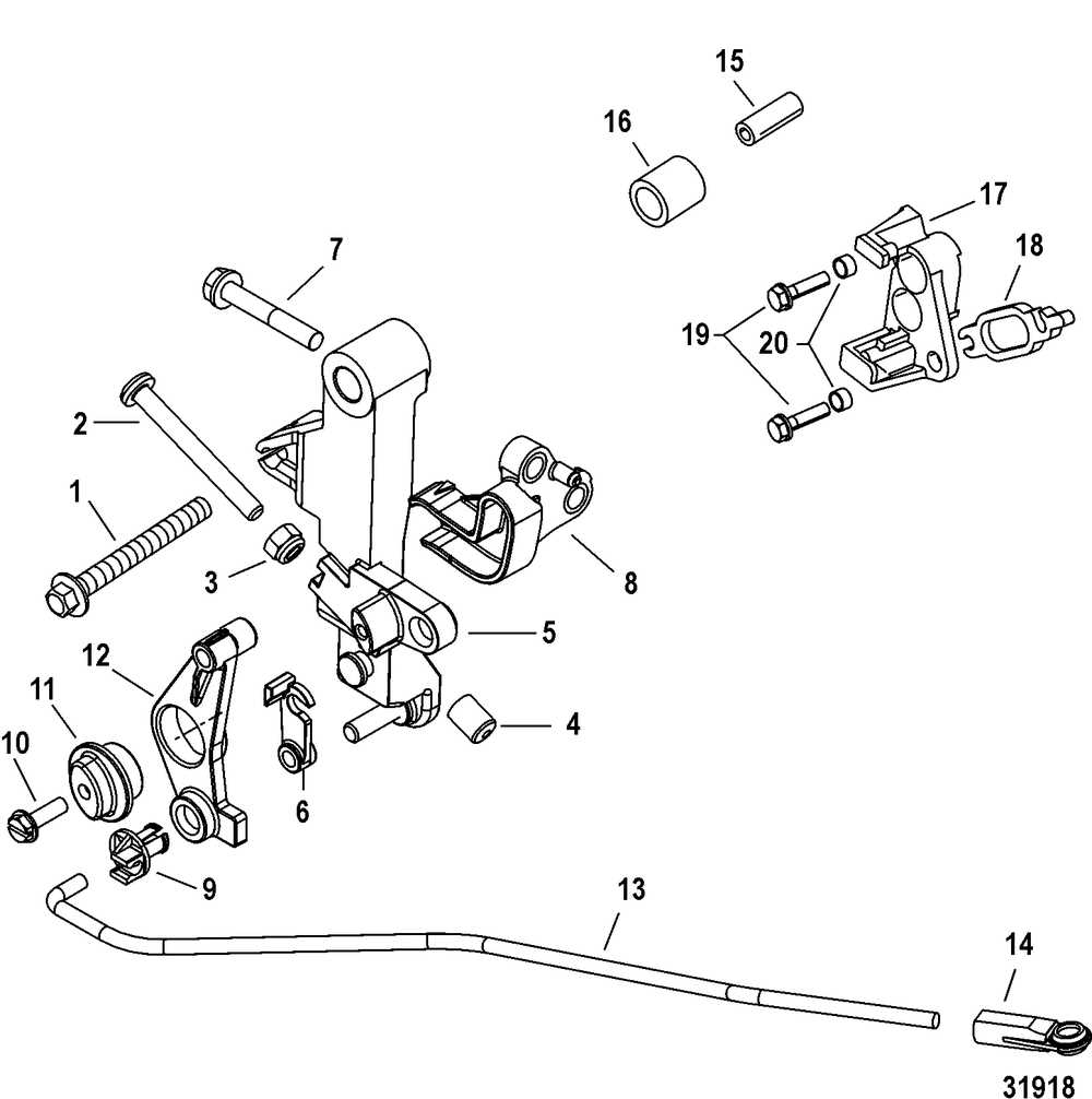
The flow of lubricating substances is designed to reach critical areas, reducing friction and dissipating heat. These pathways are intricately engineered to ensure that oil circulates effectively, covering all necessary parts. Consistent monitoring of these systems can help identify any potential blockages or leaks, which could lead to significant damage if left unaddressed. Maintaining the right viscosity of lubricants is also crucial for optimal performance.
Maintenance Practices
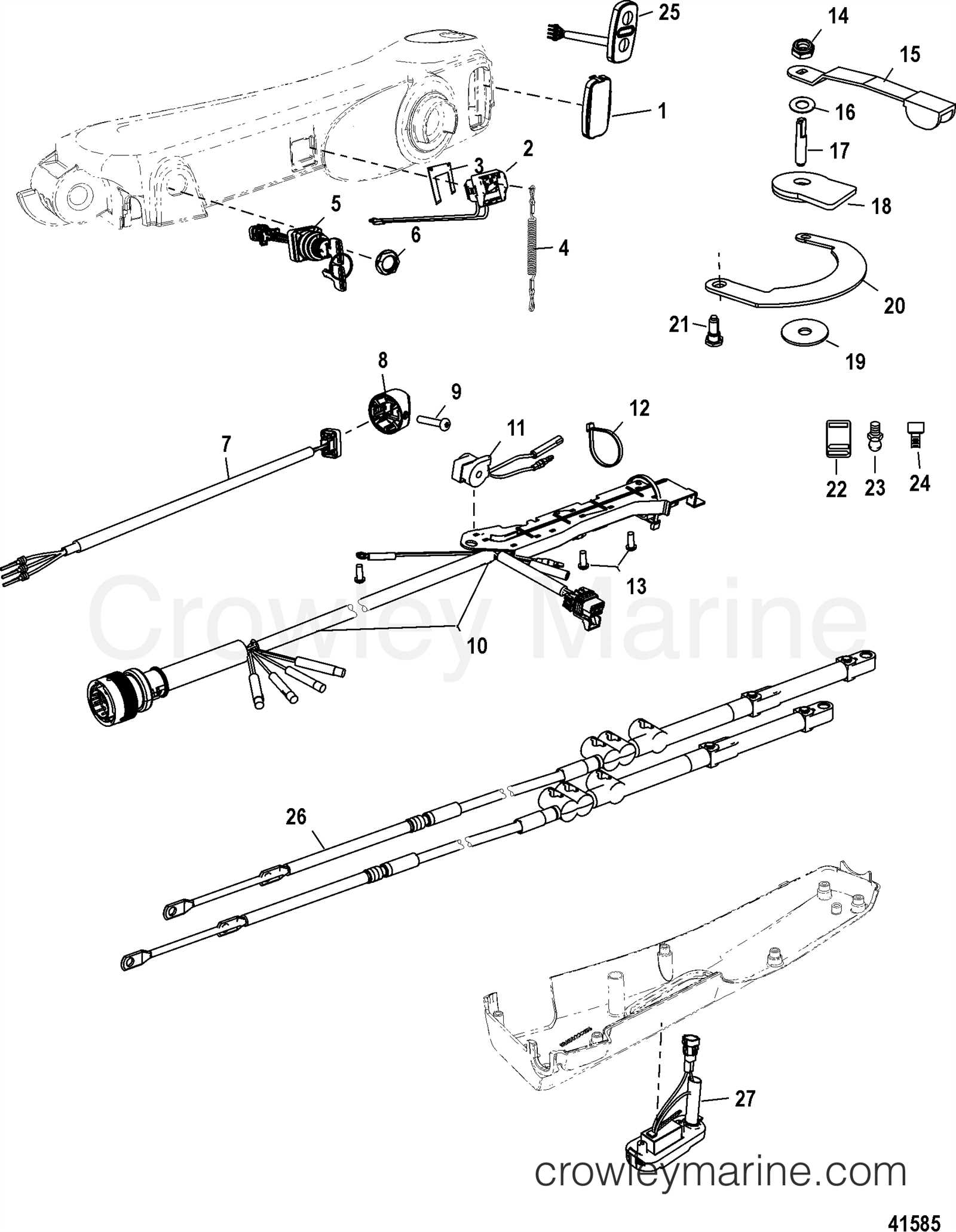
To maintain efficient operation, routine checks and timely replacements of lubricants are imperative. Utilizing high-quality substances and adhering to recommended service intervals can prevent complications. Engaging in periodic inspections of the entire lubrication system, including filters and hoses, ensures any issues are rectified promptly, safeguarding the overall functionality of the engine.
|
