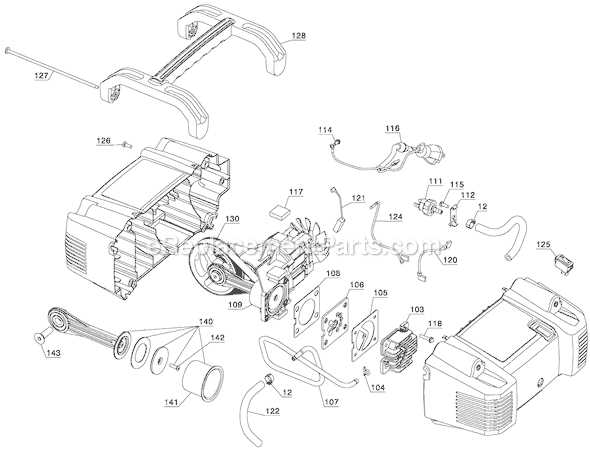
Every tool or machine is a combination of various elements that work in harmony to achieve a specific function. Understanding the internal setup and structure of these mechanisms can greatly aid in maintenance and repair, ensuring smooth operation over time. By exploring detailed layouts, you can identify each element’s role and how it interacts with others.
In this section, we will explore how to navigate through assembly charts and component arrangements. These detailed sketches provide a clear understanding of where each piece fits, helping users effectively disassemble, inspect, and reassemble their equipment. Such knowledge is crucial for ensuring optimal performance and extending the lifespan of the device.
Whether you are troubleshooting a specific issue or simply performing routine maintenance, knowing the layout of key components makes the process more efficient. Through these visual guides, you will gain a deeper insight
Understanding the Structure of Tool Diagrams
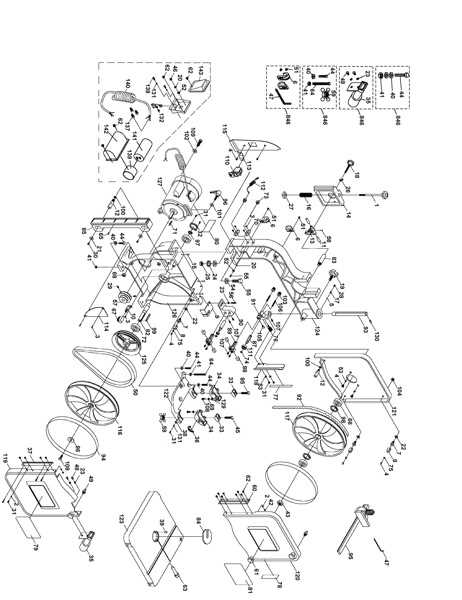
Tool diagrams provide a clear visual representation of how various components of a device are organized and interconnected. They serve as a guide for assembling, disassembling, or repairing equipment, helping users grasp the arrangement of individual elements. Understanding these illustrations is essential for efficient maintenance and troubleshooting.
Each section of a tool illustration typically highlights specific connections and mechanical relations between various parts. These schematics are carefully crafted to ensure that users can easily follow the alignment and sequence of elements, aiding in both operational and repair tasks.
Mastering the layout of such visuals can significantly improve the ability to identify issues, replace defective elements, and maintain the longevity of equipment. Whether for routine upkeep or more complex repairs, having a solid understanding of these diagrams simplifies the entire process.
Common Components in Power Tools
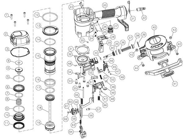
Power tools are composed of several essential elements that work together to achieve efficient performance and durability. These components vary in design but often share similar functions across different models, providing the necessary support and functionality to carry out tasks like cutting, drilling, or fastening.
Motor and Drive Mechanism
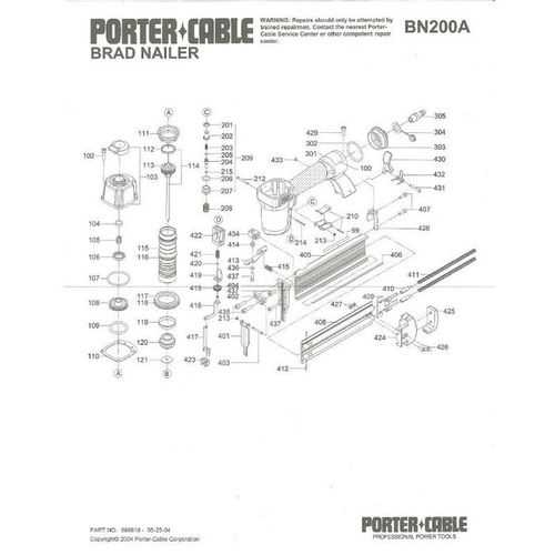
The motor is the heart of any power tool, converting electrical energy into mechanical motion. Depending on the type of tool, this motion may be rotary or linear. The drive mechanism transfers this energy to the working end, ensuring smooth operation.
Housing and Controls
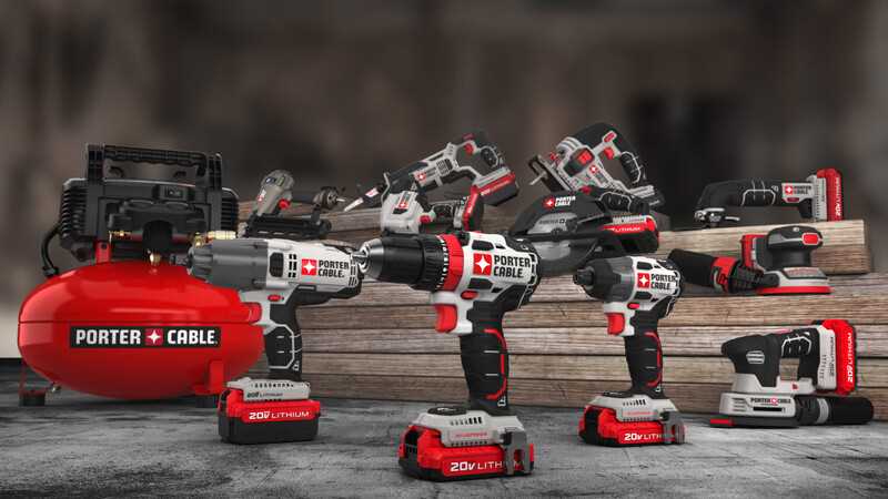
The outer casing provides protection and durability, shielding internal components from dust, moisture, and impacts. Integrated controls, such as triggers or switches, allow users to operate the tool effectively, adjusting speed or torque when needed.
- Motor – generates the required mechanical
Visualizing Parts for Effective Repairs
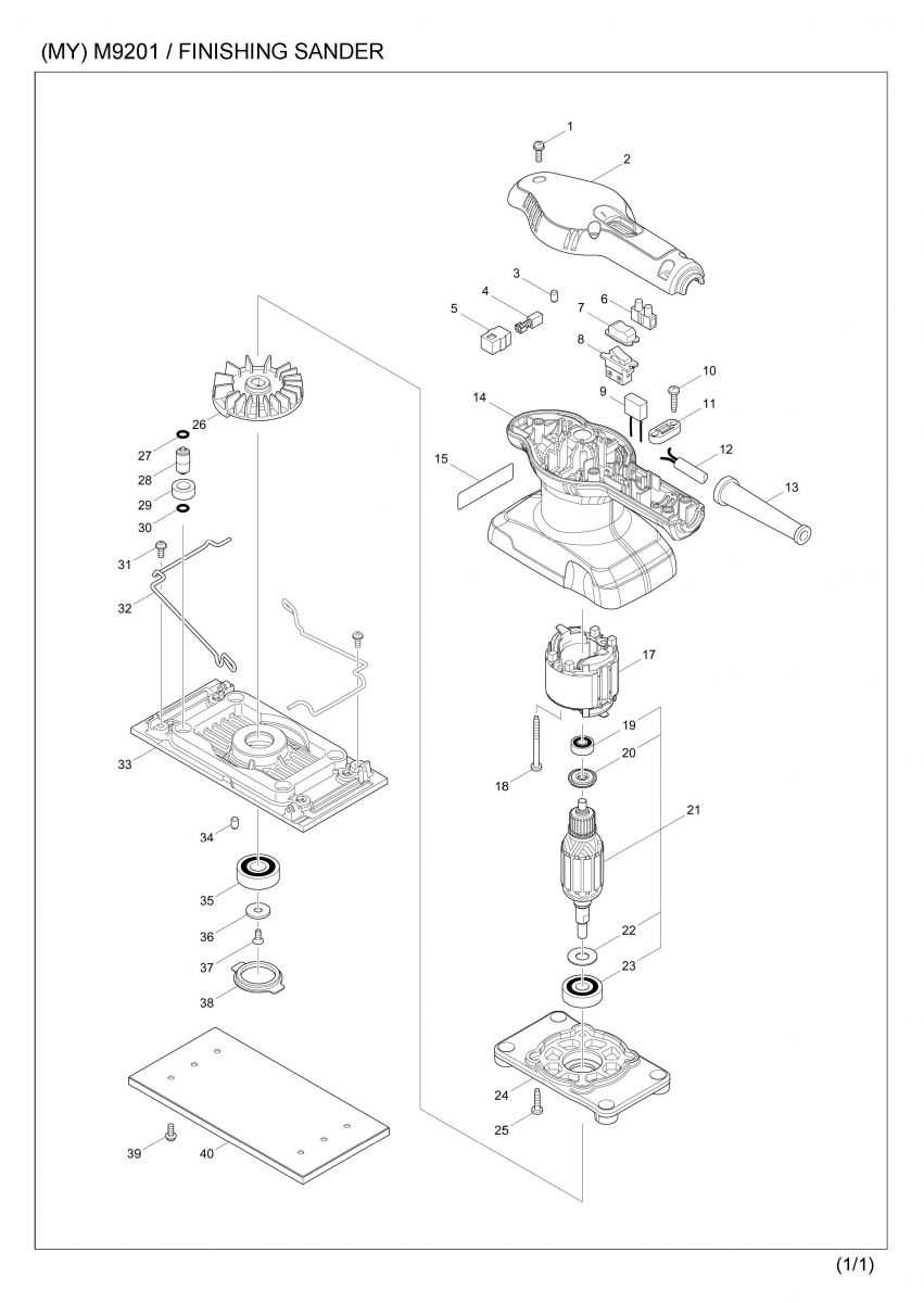
Understanding the structure of components is crucial when attempting to repair equipment efficiently. By breaking down each element and its connections, you can easily identify potential issues and find the necessary replacements. This approach helps reduce guesswork and saves time, leading to more accurate and lasting fixes.
Step-by-Step Breakdown
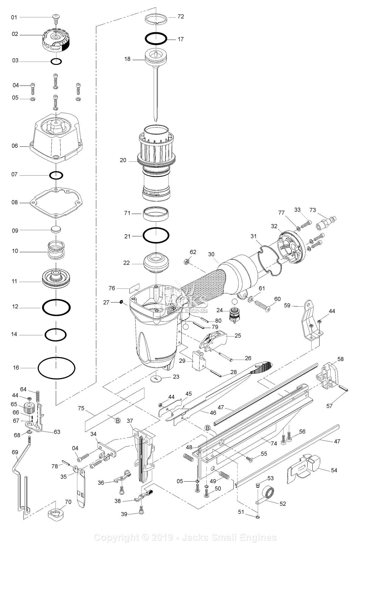
- Start by examining the overall assembly to identify key areas that require attention.
- Note the positioning and relationship of each component within the system.
- Determine which elements are essential for the functionality and which can be tested or replaced first.
Organizing Components for Clarity
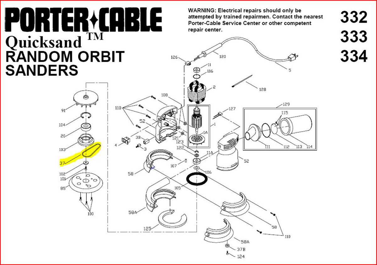
- Group similar elements together based on their function.
- Create a clear labeling system to avoid confusion during reassembly.
- Use sketches or notes to map out connections between elements for reference during repairs.
Identifying Key Elements in Assembly
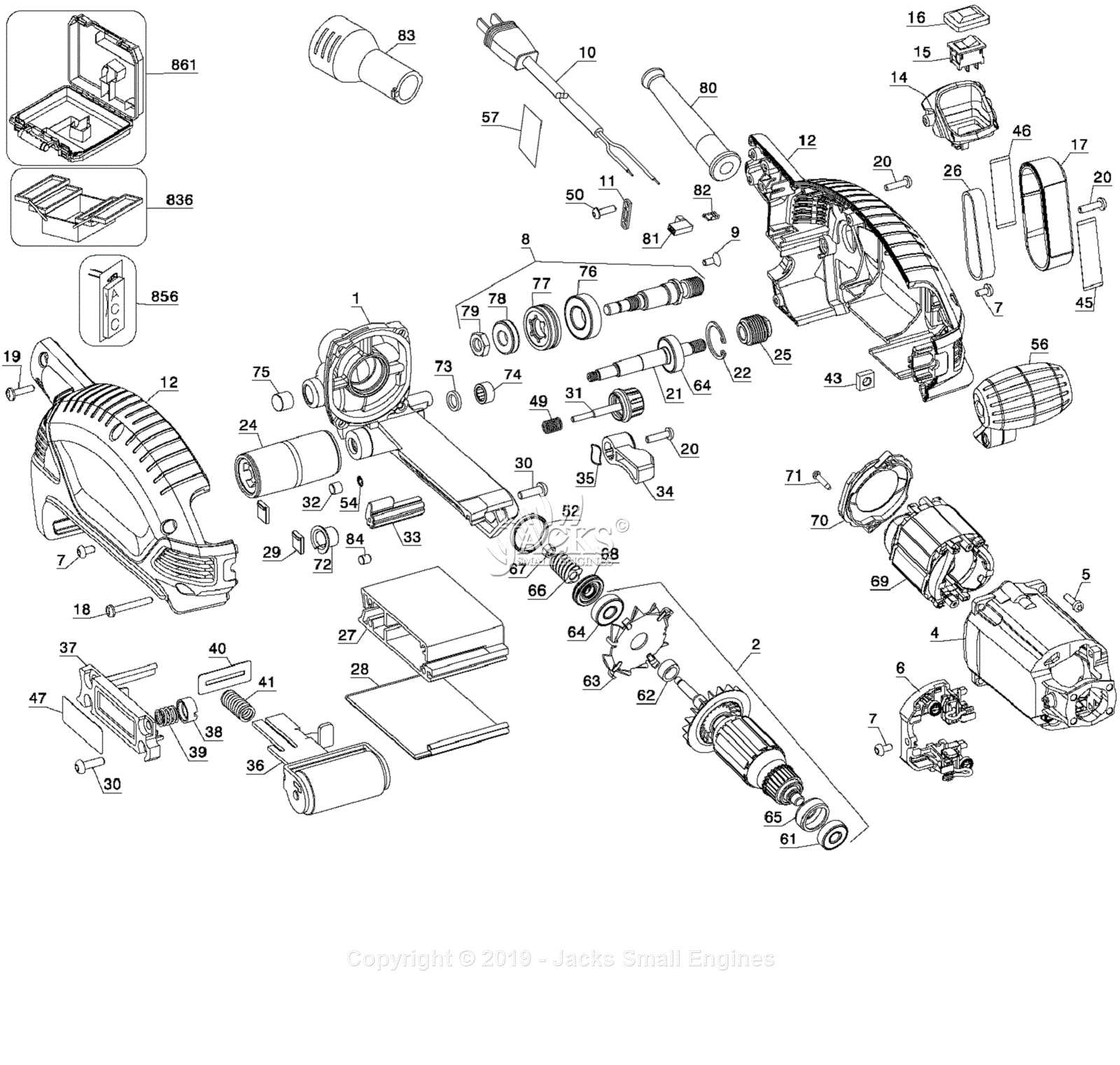
Understanding the crucial components during the assembly process is essential for ensuring proper functionality and longevity. Recognizing individual sections and their interactions allows for smoother installation and reduces the likelihood of errors. By examining the main elements carefully, you can avoid common mistakes and ensure each piece fits perfectly into the overall structure.
Here are several primary areas to focus on:
- Fasteners and screws: These small components hold everything together and ensure stability.
- Mounting points: Correct alignment of the main sections is crucial for operational efficiency.
- Mechanical components: Gears, levers, and moving parts that are key to functionality.
- Power connections: Ensuring proper wiring and contact is essential for the system’s operation.
Identifying these components early in the process will aid in smoother assembly and contribute to the overall performance of the device.
Locating Replacement Parts Easily
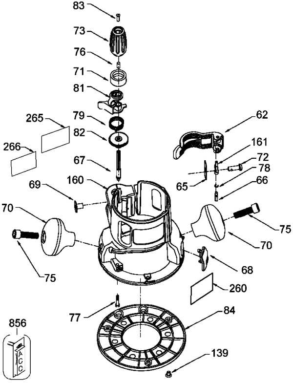
Finding the right components for tool repairs can be a straightforward process when you know where to look. Understanding how to navigate different resources and knowing what to search for can save both time and effort. Here’s a guide to help you streamline this task.
- Start by identifying the specific item you need. This could be based on a model number, a serial label, or the name of the device you’re working with.
- Consult user manuals or technical documents that often include detailed breakdowns of the equipment and its assembly.
- Online resources can offer visual layouts, which make it easier to match the necessary component to its correct position.
- When in doubt, customer service or technical support from the manufacturer can help guide you through the identification process.
By utilizing these methods, you
Interpreting Diagrams for Accurate Maintenance
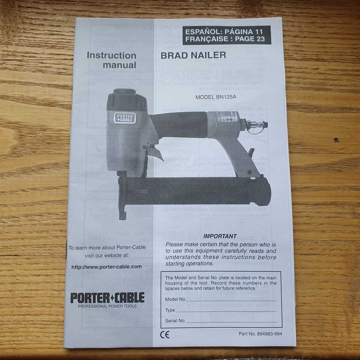
Understanding visual representations of complex systems is essential for ensuring proper upkeep and repair. These schematics provide critical insights into how components interact and help identify the necessary elements for service tasks. By carefully analyzing the layout, users can prevent errors and achieve precise restoration.
The following table outlines common elements found in such diagrams and how they contribute to efficient maintenance work:
Symbol Description Purpose Circles or Nodes Represent connection points Indicate areas where components interface How to Use Diagrams for Troubleshooting
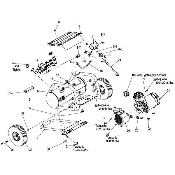
Utilizing visual representations can significantly enhance the troubleshooting process for various devices and machinery. These illustrations provide clear insights into the components and their interconnections, enabling users to identify issues more effectively. By following a systematic approach, one can leverage these resources to diagnose problems swiftly and accurately.
Step 1: Begin by examining the overall layout depicted in the visual guide. Understand how the elements are arranged and their intended functions. This foundational knowledge is crucial for recognizing deviations from normal operation.
Step 2: Next, focus on specific areas where malfunctions are suspected. Identify the relevant components and trace their connections as shown in the representation. This will help isolate the problem and clarify which parts may need further inspection or replacement.
Step 3: Finally, cross-reference your findings with the accompanying notes or specifications, if available. This can provide additional context and may reveal common issues or solutions associated with the identified components. By applying these strategies, troubleshooting can become a more structured and efficient task.
Benefits of Detailed Tool Breakdown
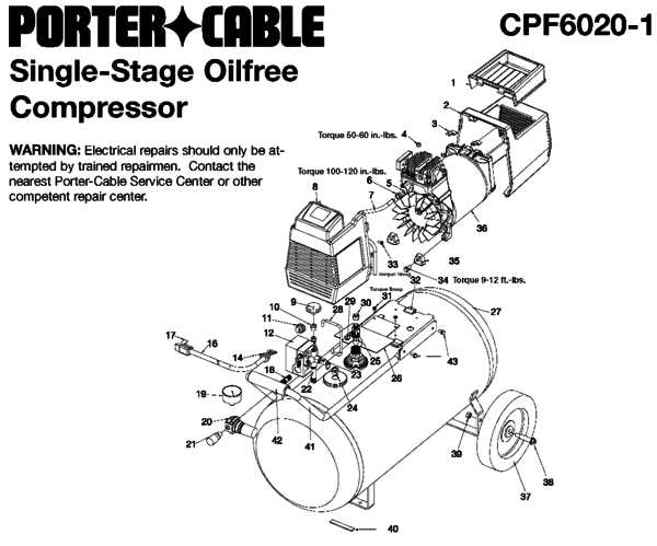
Understanding the intricacies of tools and their components provides several advantages that enhance usability and maintenance. A thorough exploration of individual elements contributes to better performance and informed decision-making during repairs or upgrades.
- Improved Maintenance: Recognizing each component’s role aids in identifying potential issues, allowing for proactive maintenance.
- Enhanced Repair Skills: Familiarity with the various parts equips users with the knowledge necessary to perform repairs efficiently.
- Informed Purchases: Awareness of specific components enables informed decisions when selecting replacements or upgrades.
- Increased Lifespan: Proper understanding of tool components can lead to better care, extending the overall lifespan of the equipment.
- Optimized Performance: Knowing how each part functions together ensures optimal operation, maximizing the tool’s capabilities.
Ultimately, a detailed breakdown fosters a deeper connection with the tools, empowering users to utilize them more effectively and confidently.
Best Practices for Diagram Analysis
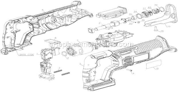
Understanding visual representations of components is crucial for effective troubleshooting and maintenance. This section outlines key approaches to enhance your ability to interpret these illustrations efficiently and accurately.
1. Familiarize Yourself with Symbols: Different illustrations utilize specific symbols to represent various elements. Spend time learning these notations to facilitate smoother analysis.
2. Focus on Connections: Pay attention to how components are interconnected. Understanding these relationships can provide insight into the overall functionality and help identify potential issues.
3. Use Annotations: Adding notes and highlights can aid in clarifying complex areas. Mark important sections to quickly reference them during future analyses.
4. Refer to Manufacturer Guidelines: Manufacturers often provide resources that clarify their representations. Consult these materials to ensure accurate interpretation.
5. Practice Regularly: Like any skill, improving your understanding of these representations takes practice. Regularly engaging with different illustrations will build your confidence and proficiency.
By implementing these strategies, you can enhance your analytical skills and make informed decisions based on visual representations of components.