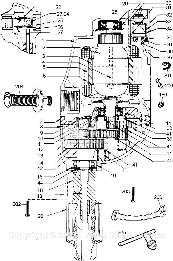
In the realm of mechanical craftsmanship, various instruments play a pivotal role in achieving accuracy and efficiency. Among these, a specific apparatus stands out, known for its ability to enhance productivity in woodworking and metalworking. This exploration aims to illuminate the essential elements that contribute to the functionality of this remarkable tool.
Each element serves a unique purpose, working in harmony to enable precise operations. From the base to the control mechanisms, understanding these components can significantly improve one’s ability to utilize the tool effectively. By delving into the specifics, enthusiasts and professionals alike can gain insights into the ultimate capabilities of this indispensable equipment.
Whether for hobbyists or seasoned craftsmen, recognizing the significance of each segment fosters a deeper appreciation for the craftsmanship involved. As we navigate through this intricate web of features, we uncover the intricate relationships that define the tool’s overall performance.
Understanding Drill Press Components
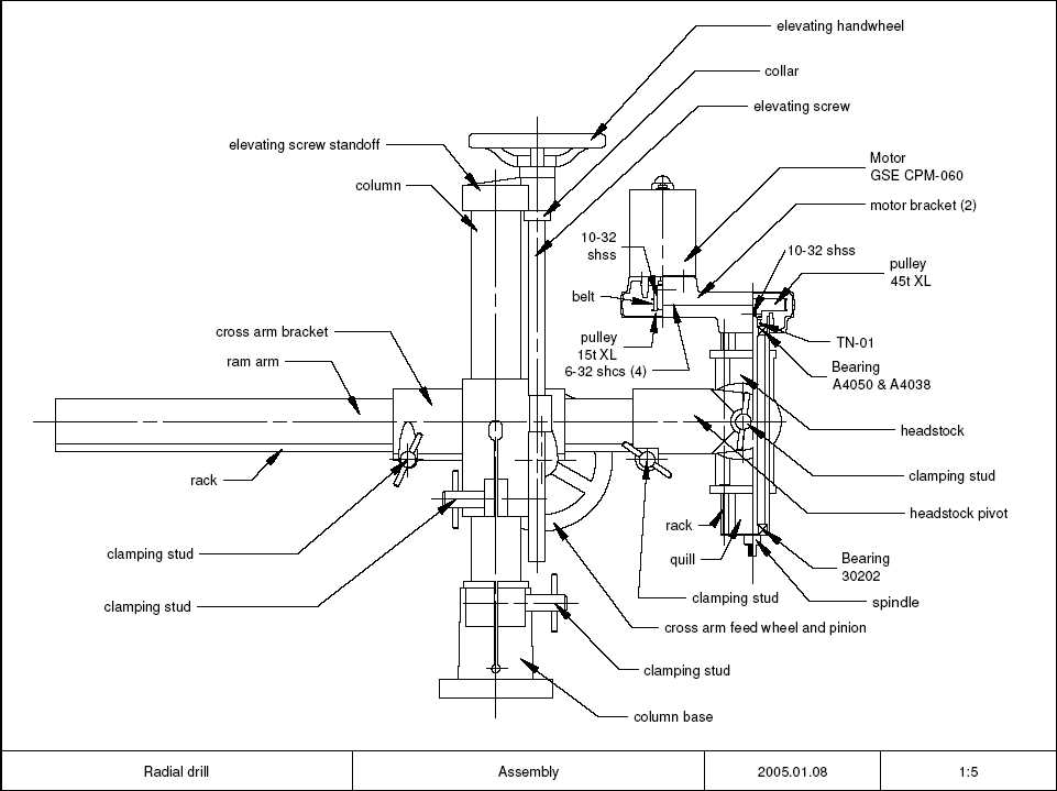
Gaining familiarity with the essential elements of a machining tool enhances both its operation and maintenance. Each component plays a crucial role in the overall functionality and precision of the equipment, contributing to efficient performance and quality results.
Main Elements
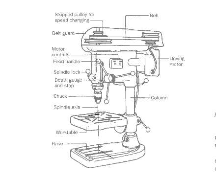
- Motor: The power source that drives the entire mechanism.
- Column: A sturdy vertical structure providing stability and support.
- Table: A flat surface where materials are positioned for work.
- Spindle: A rotating shaft that holds and drives the cutting tool.
- Feed Handle: The control used to adjust the depth of the cutting action.
Supporting Features
- Base: The foundation that ensures the tool remains steady during use.
- Quill: A mechanism that allows for vertical movement of the spindle.
- Chuck: The device that secures the tool in place.
- Adjustment Controls: Features that enable precise settings for various operations.
Understanding these fundamental components allows users to maximize the capabilities of the machinery, ensuring accurate and efficient outcomes in their projects.
Overview of a Drill Press Diagram
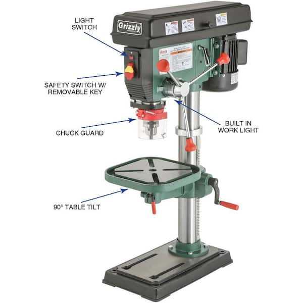
This section provides a comprehensive look at the essential components of a vertical machining tool. Understanding the configuration and function of each element is crucial for effective usage and maintenance. A well-structured illustration can significantly enhance one’s grasp of how this equipment operates.
Key Features: The visual representation serves as a guide to identify and familiarize oneself with the critical functions of the apparatus. Each component plays a vital role in the overall efficiency and precision of the operations performed.
Utility and Function: The arrangement not only aids in recognizing individual elements but also highlights their interrelationships, demonstrating how they collectively contribute to the tool’s performance. Analyzing this visual can lead to improved techniques and enhanced outcomes in various tasks.
Functionality of Key Parts
This section explores the essential components of a specific tool used in various workshops, focusing on their roles and contributions to the overall effectiveness of the equipment. Each element plays a significant part in ensuring precision and reliability during operations.
The base provides stability, anchoring the machine securely to the work surface. This foundation absorbs vibrations and minimizes movement, allowing for accurate execution of tasks.
The column serves as the vertical support structure, enabling the movement of the cutting mechanism up and down. Its height is adjustable, facilitating work with materials of varying thicknesses.
The head houses the motor and mechanism that drives the tool, delivering the necessary power for operation. It is designed to ensure that the rotational force is transmitted effectively to the cutting bit.
The table offers a platform for securing the material being worked on. Its adjustability in both height and angle allows for versatile positioning, catering to different types of projects and user preferences.
The feed mechanism regulates the rate at which the cutting bit descends into the material. This control is vital for achieving desired results, as it affects both the quality of the cut and the longevity of the tool.
Finally, the depth stop provides a crucial safety feature, allowing users to set a specific depth for the cutting process. This ensures consistent results and prevents accidental over-penetration, enhancing both precision and safety during use.
Base and Column: Structural Elements
The foundation and vertical support of a tool are crucial for its stability and precision during operation. These elements serve as the backbone, ensuring that the entire structure remains balanced and securely anchored. Understanding their roles enhances the appreciation of the overall functionality.
The base is typically the lowest component, providing the necessary weight and stability. Key features include:
- Weight Distribution: A heavy base minimizes vibrations and maintains steadiness.
- Footprint: A broad surface area helps in preventing tipping.
- Material: Often constructed from solid materials like cast iron for durability.
The column acts as the main vertical support, connecting the base to the operational components above. Its characteristics include:
- Height: Determines the reach and capability of the tool.
- Strength: Must withstand various forces during use without bending.
- Alignment: Ensures that all upper mechanisms are positioned correctly for accurate operation.
Together, these structural components not only enhance performance but also contribute to the safety and efficiency of the entire apparatus.
Table Adjustments and Features
The functionality of a machining tool heavily relies on the versatility and precision of its support surface. This component plays a crucial role in stabilizing the workpiece, allowing for accurate operations and a variety of setups. Understanding how to manipulate and utilize this element effectively can significantly enhance the user experience and the quality of the final product.
One of the key features to consider is the ability to tilt and swivel the platform. This adjustability enables users to work at different angles, accommodating various project requirements. Additionally, many surfaces come equipped with T-slots, facilitating the secure attachment of clamps or other fixtures, which further aids in stabilizing the workpiece during operation.
Height adjustments are another essential aspect, allowing the user to position the workpiece at an optimal level for comfort and efficiency. Smooth movement is critical in this regard, as it ensures precise alignment with the cutting tool. Furthermore, certain models include built-in measuring scales, which enhance accuracy by providing instant references for height adjustments.
Finally, the overall design of the support surface can impact the user’s workflow. A larger and more robust area can accommodate bigger materials, while surfaces with integrated storage options promote organization, ensuring that essential tools are always within reach. Understanding these features can lead to improved results and a more enjoyable experience in any machining endeavor.
Drill Head and Its Mechanisms
The upper assembly of a boring tool is essential for precision and efficiency in various tasks. This component encompasses several critical mechanisms that enable effective operation and control.
- Spindle: The rotating shaft that holds and drives the cutting tool.
- Chuck: A clamping device that secures the tool in place.
- Feed Mechanism: Controls the depth and speed of the boring operation.
- Pulleys and Belts: Transmit power from the motor to the spindle.
- Motor: Provides the necessary energy for operation.
Understanding these components helps in mastering the tool’s functionality and enhances the overall effectiveness of any project.
Motor Types in Drill Presses
Understanding the different types of motors used in these machines is essential for selecting the right equipment for specific tasks. Each motor type offers unique characteristics that influence performance, efficiency, and suitability for various applications. The choice of motor can significantly impact operational capabilities and overall user experience.
| Motor Type | Characteristics | Applications |
|---|---|---|
| Induction Motor | Reliable, efficient, low maintenance | General purpose, heavy-duty tasks |
| Brushless DC Motor | High efficiency, longer lifespan, quiet operation | Precision work, variable speed applications |
| Universal Motor | High speed, versatile, compact | Light-duty, portable applications |
| Stepper Motor | Accurate positioning, controllable increments | CNC operations, detailed tasks |
Choosing the right motor is crucial for achieving optimal performance and meeting the specific demands of various projects. Each type offers distinct advantages that cater to different needs and environments.
Safety Features and Controls
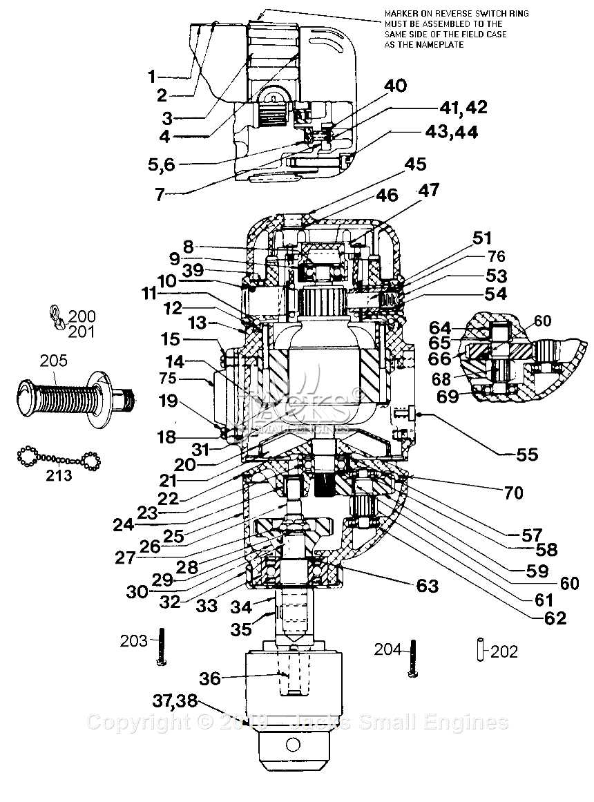
Ensuring a secure environment during operation is crucial for optimal performance and user protection. Various mechanisms are implemented to minimize risks and enhance safety, allowing users to focus on their tasks without unnecessary concern.
Emergency Shutoff
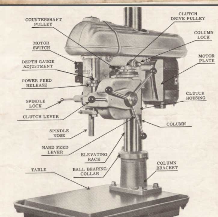
An essential element in any machine is the emergency shutoff switch. This feature enables quick cessation of operations in critical situations, ensuring that users can react promptly to avoid accidents.
Guarding Mechanisms
Protective barriers and covers play a vital role in safeguarding users from moving components and debris. These features are designed to keep hands and other body parts at a safe distance, thereby reducing the likelihood of injury during usage.
Common Maintenance Practices
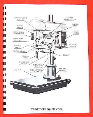
Regular upkeep is essential for ensuring optimal performance and longevity of equipment in any workshop environment. Adopting a proactive approach to maintenance can prevent unexpected failures and enhance efficiency. This section highlights fundamental practices that contribute to reliable operation.
Cleaning: Keeping the machine clean is crucial. Dust, debris, and residual materials can accumulate, affecting functionality. Regularly wipe down surfaces and remove any buildup from the mechanisms to maintain smooth operation.
Lubrication: Proper lubrication of moving components is vital to minimize friction and wear. Use appropriate oils or greases as specified by the manufacturer. Regularly check and replenish lubricants to ensure all parts operate seamlessly.
Inspection: Frequent checks for signs of wear or damage can prevent serious issues. Examine belts, pulleys, and other critical components for cracks or deterioration. Identifying problems early can save time and resources in the long run.
Calibration: Regularly calibrating the machine ensures accuracy and precision in its operations. Follow the manufacturer’s guidelines to adjust settings and verify alignment, maintaining the quality of the results.
Storage: When not in use, protect the equipment from environmental factors. Store in a dry, dust-free area and consider using covers to shield against moisture and dirt.
Implementing these maintenance practices not only extends the life of the equipment but also enhances the safety and productivity of the workspace. Regular attention to these areas is a worthwhile investment for any operator.