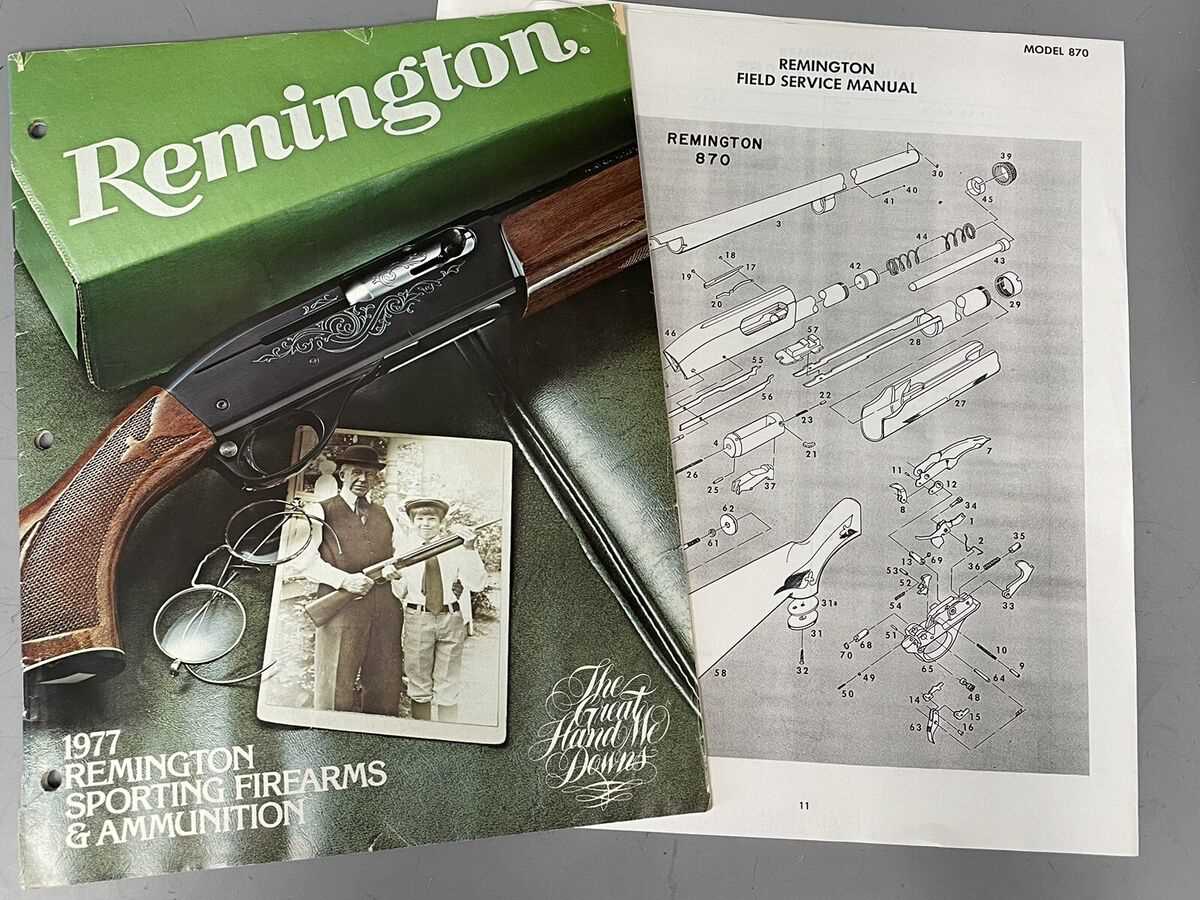
In the realm of machinery and engineering, comprehending the arrangement of various elements is crucial for both assembly and maintenance. A visual representation serves as an essential guide, allowing technicians and enthusiasts to identify each segment’s function and relationship with others. This clarity not only aids in effective repairs but also enhances overall operational efficiency.
When delving into the intricacies of these illustrations, one can appreciate the meticulous organization of each unit. By studying the interconnections and placements, users gain valuable insights into the operational dynamics. Such knowledge empowers individuals to tackle issues with confidence, ensuring that they can restore functionality seamlessly.
Moreover, these comprehensive layouts are not just useful for troubleshooting; they also play a pivotal role in the design process. Understanding how each component interacts helps engineers innovate and improve existing systems. The thoughtful arrangement of elements can lead to enhanced performance and durability, ultimately contributing to the advancement of technology.
Understanding the 870 Parts Diagram
Grasping the layout of a complex assembly is essential for effective maintenance and repair. Each component plays a vital role, and recognizing how they interconnect can enhance your overall comprehension of the system. This section aims to provide insights into the intricacies of such a schematic, facilitating better handling and troubleshooting of the equipment.
Importance of Familiarity
Being well-acquainted with the configuration allows users to identify parts swiftly, leading to more efficient diagnostics. Understanding the relationship between various elements not only aids in repairs but also ensures that modifications are executed correctly. Each segment is designed with a specific function, and knowledge of these roles can prevent potential errors during usage.
Visual Learning and Application
Utilizing visual aids can significantly enhance your grasp of the assembly’s structure. Visual representations provide a clear map, enabling easier navigation through the various components. Engaging with these illustrations fosters a deeper understanding, allowing users to visualize the entire mechanism in action. Emphasizing hands-on experience alongside visual study can solidify knowledge and improve overall proficiency.
Importance of Parts Diagrams in Machinery
Understanding the intricate workings of equipment is crucial for effective maintenance and operation. Visual representations play a vital role in illustrating the components and their interrelationships, enabling operators and technicians to grasp complex systems quickly. These depictions serve as essential tools for both training and troubleshooting, facilitating a deeper comprehension of machinery functions.
Enhancing Maintenance Efficiency
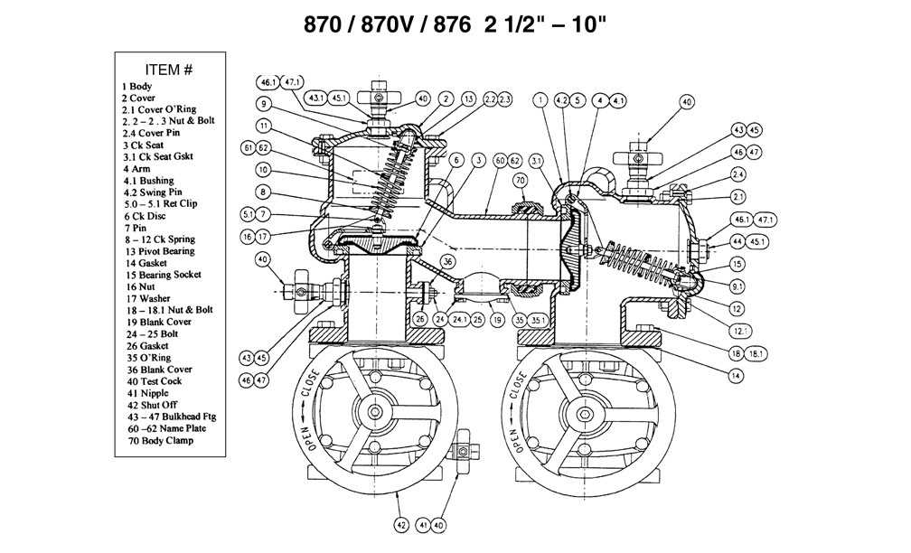
Accurate visual aids simplify the identification of individual elements within a machine, allowing for swift assessments during repairs. By referring to these illustrations, maintenance personnel can efficiently locate and address issues, reducing downtime and improving overall productivity. This clarity is particularly beneficial in environments where time is critical.
Supporting Training and Skill Development

For new employees, visual guides offer an accessible way to learn about machinery without overwhelming them with technical jargon. These illustrations serve as educational resources that enhance understanding and retention of information, promoting safer and more effective operation practices. As a result, both novice and experienced staff can benefit from a more structured approach to mastering the equipment they work with.
Components Illustrated in the 870 Diagram

This section explores the various elements represented in the visual representation, highlighting their functions and interrelationships within the overall system. Understanding these components is crucial for comprehending how they contribute to the effective operation and maintenance of the machinery.
Key Elements and Their Functions
Each element plays a specific role in ensuring optimal performance. For instance, the main housing protects internal mechanisms while facilitating necessary airflow for cooling. Additionally, connectors allow for seamless integration with other systems, enhancing versatility and usability. Understanding these functions can aid in troubleshooting and repairs.
Interconnections and Synergy
The synergy between components is essential for efficiency. For example, the coupling of the drive system with the control unit ensures precise operation. When these elements work together harmoniously, they minimize wear and maximize longevity. Recognizing these relationships can provide insights into potential areas for enhancement or adjustment.
How to Read a Parts Diagram
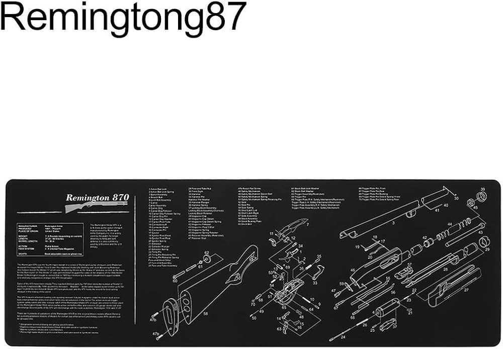
Understanding an assembly illustration is crucial for effective maintenance and repairs. These visual aids provide a clear representation of components, helping you to identify their arrangement and functionality within a system.
To effectively interpret such illustrations, follow these key steps:
- Familiarize Yourself with the Legend:
- Most illustrations include a legend that explains symbols and color coding.
- Take note of any specific notation related to sizes or materials.
- Identify Main Components:
- Locate the major elements depicted in the visual aid.
- Understand how these elements interact with each other.
- Follow the Flow:
- Observe the directional arrows or lines that indicate movement or connection.
- This will help you grasp the operational sequence of the system.
- Cross-Reference with Documentation:
- Consult manuals or technical documents for additional context.
- This can provide deeper insights into specific parts and their functions.
By mastering these techniques, you will enhance your ability to navigate and utilize these visual representations effectively, leading to more successful repairs and maintenance tasks.
Common Issues Identified with Diagrams
Visual representations play a crucial role in conveying complex information efficiently. However, various challenges often arise during their creation and interpretation, which can lead to misunderstandings and inefficiencies. Addressing these issues is essential for improving clarity and ensuring that the intended message is effectively communicated.
One common problem is the lack of standardization in symbols and notations. Different creators may use varying symbols to represent the same concepts, causing confusion among users. This inconsistency can hinder collaboration and lead to errors in understanding.
Another frequent issue is overcrowding. When too much information is packed into a single visual, it becomes difficult for viewers to focus on the key elements. A clear and concise layout is vital to enhance comprehension and retention.
Inaccurate scaling also presents significant challenges. When proportions are not accurately represented, it can mislead users regarding the relationships between components. Ensuring that sizes and distances are appropriately scaled is crucial for accurate interpretation.
Lastly, insufficient labeling can result in ambiguity. Clear and descriptive labels are necessary for guiding viewers through the visual. Without adequate annotations, users may struggle to grasp the context and meaning of the depicted elements.
Maintenance Tips Using the 870 Diagram
Proper upkeep of machinery is essential for optimal performance and longevity. Utilizing a comprehensive visual guide can significantly enhance the maintenance process, allowing for easy identification and troubleshooting of components. Here are some practical suggestions to keep in mind.
- Regularly consult the visual reference to familiarize yourself with the components and their arrangement.
- Perform routine inspections to detect any signs of wear or damage.
- Follow the recommended schedules for lubrication and replacement of key elements to prevent failures.
When addressing issues, consider the following steps:
- Identify the specific area of concern using the visual reference.
- Assess the condition of related components to prevent cascading failures.
- Document any findings and actions taken for future reference.
Maintaining a proactive approach ensures that the machinery operates efficiently, minimizing downtime and repair costs.
Sources for Accurate Diagram Information
When seeking precise representations of mechanical components, identifying reliable resources is crucial. Accurate visual guides serve as essential tools for both professionals and enthusiasts, facilitating effective maintenance and assembly. The following sections explore various avenues to access trustworthy information, ensuring that users can confidently navigate complex systems.
Official Manufacturer Resources
One of the most dependable sources for authentic representations is the official documentation provided by manufacturers. These documents often include comprehensive illustrations and specifications tailored to specific models. Utilizing manuals, service guides, and technical bulletins directly from the source guarantees that users are referencing the latest updates and recommendations.
Community Forums and Expert Websites

Engaging with dedicated online communities can yield valuable insights and shared resources. Forums and websites maintained by experts often feature user-generated content, including detailed sketches and practical advice. These platforms not only foster collaboration but also provide a space for troubleshooting and sharing best practices, enriching the understanding of intricate designs.
Updating Your Machinery with Diagrams
In the fast-paced world of industrial operations, keeping equipment up-to-date is crucial for maintaining efficiency and safety. Visual representations serve as invaluable tools for understanding the intricate workings of machinery. By utilizing these resources, operators can streamline maintenance processes, enhance troubleshooting efforts, and ultimately improve overall performance.
Benefits of Visual Aids
Visual aids simplify complex information, making it accessible to technicians and operators alike. They help in identifying components quickly and facilitate effective communication among team members. Furthermore, these illustrations can significantly reduce downtime, as they allow for faster identification of issues and the implementation of necessary adjustments.
Implementing Effective Updates
To ensure that your equipment remains at peak performance, regularly updating these visual resources is essential. Incorporating new findings, modifications, or improvements into your visual documentation keeps everyone informed and prepared for any challenges that may arise. This proactive approach not only enhances operational efficiency but also fosters a culture of continuous improvement within your organization.
Comparing Different Parts Diagrams
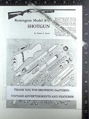
Analyzing various schematics provides valuable insights into the design and functionality of machinery. By evaluating different illustrations, one can understand how components interact and identify potential improvements in structure and efficiency. Each representation may vary in detail, layout, and clarity, influencing the ease of comprehension for users.
| Type | Description | Advantages | Disadvantages |
|---|---|---|---|
| Schematic | A simplified representation highlighting the relationships between elements. | Easy to read and understand; useful for conceptual overview. | Lacks specific details; may not represent real-world configurations. |
| Exploded View | A three-dimensional illustration that shows components separated from their assembly. | Provides a clear view of how parts fit together; excellent for assembly guidance. | Can be complex; may overwhelm users with too much information. |
| Technical Drawing | A detailed representation that includes measurements and specifications. | Highly precise; essential for manufacturing and engineering purposes. | May be difficult for non-experts to interpret; requires technical knowledge. |
Each style serves distinct purposes and caters to different audiences, making it crucial to select the appropriate format for specific tasks. Understanding the strengths and weaknesses of each representation can enhance both communication and functionality in technical fields.