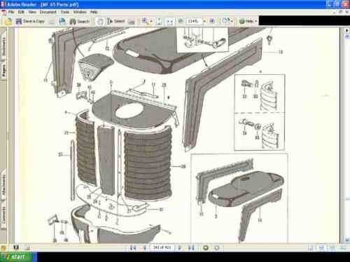
In the world of vintage agricultural machinery, comprehending the intricate structure of a renowned model is essential for enthusiasts and mechanics alike. These machines, celebrated for their reliability and performance, often require a detailed exploration of their individual elements to ensure optimal functionality.
Exploring the specific layout of these mechanisms not only enhances maintenance but also allows for effective troubleshooting and repairs. By examining a visual representation of the various components, users can easily identify and address issues that may arise over time.
This guide aims to provide clarity on the assembly and configuration of a particular classic tractor, facilitating a deeper appreciation for its engineering. With a comprehensive understanding, operators can maximize the lifespan and efficiency of these remarkable machines.
Massey Ferguson 65 Overview
The model in question represents a significant piece of agricultural machinery, known for its durability and efficiency. Designed to meet the demands of modern farming, it combines innovative engineering with practical features that enhance productivity on the field. This model has established a reputation for reliability, making it a preferred choice among farmers and agricultural professionals.
Key Features
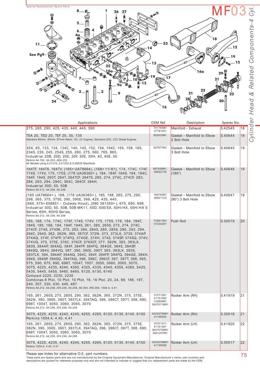
This robust vehicle comes equipped with several essential attributes that facilitate various farming tasks. Its design promotes ease of use while ensuring powerful performance. Key aspects include:
| Feature | Description |
|---|---|
| Engine | High-performance engine that provides excellent torque and efficiency. |
| Transmission | Smooth shifting system that allows for seamless operation across different terrains. |
| Hydraulics | Advanced hydraulic system that enhances lifting capabilities for various attachments. |
Applications
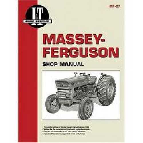
This agricultural machine is versatile, suitable for a range of applications including plowing, tilling, and hauling. Its adaptability ensures that it can be utilized effectively in various farming scenarios, from small family farms to larger agricultural enterprises. Users appreciate its ease of maintenance and the availability of support, further solidifying its status as a vital asset in modern agriculture.
Importance of Parts Diagrams
Visual representations of components play a crucial role in the maintenance and repair of machinery. They serve as essential tools that enhance understanding, streamline troubleshooting, and ensure the efficient assembly and disassembly of various elements. By providing a clear overview of how different parts interconnect, these illustrations facilitate more effective repairs and upgrades.
When dealing with complex equipment, the absence of these visual aids can lead to confusion and errors. Accurate depictions help users identify specific components quickly, saving time and reducing the risk of mistakes during repairs. Moreover, these resources can enhance communication between technicians and operators, ensuring everyone is on the same page when discussing maintenance tasks.
| Benefits | Description |
|---|---|
| Clarity | Offers a clear visual guide for understanding component relationships. |
| Efficiency | Speeds up the troubleshooting process by enabling quick identification of issues. |
| Communication | Facilitates better dialogue among team members regarding repair and maintenance. |
| Accuracy | Reduces the likelihood of errors during assembly or disassembly tasks. |
In summary, these visual aids are invaluable assets for anyone involved in the upkeep of machinery. Their role in promoting understanding and accuracy cannot be overstated, making them essential for effective operation and maintenance.
Identifying Key Components
Understanding the essential elements of machinery is crucial for effective maintenance and repair. By recognizing the main constituents, operators can ensure optimal performance and longevity of their equipment. This knowledge not only facilitates troubleshooting but also aids in planning for future upgrades and replacements.
Essential Parts Overview
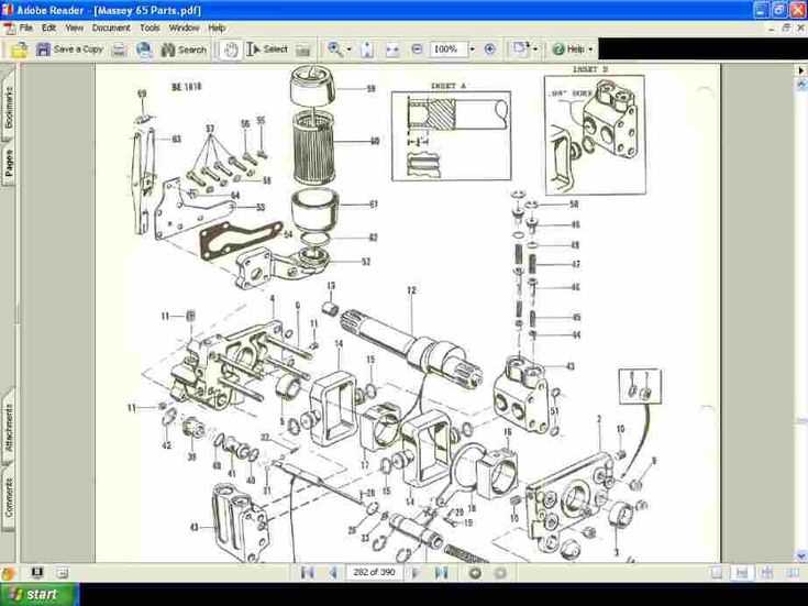
Every piece of machinery consists of specific components that serve distinct functions. These include the engine, transmission, hydraulic system, and electrical elements. Familiarity with these key areas allows for better handling and quicker diagnosis of issues that may arise during operation.
Importance of Component Familiarity
Being well-versed in the various parts enhances safety and efficiency. Operators who can identify and assess the condition of critical components are better equipped to implement timely interventions, ultimately minimizing downtime and maximizing productivity.
Common Replacement Parts Explained
When it comes to maintaining agricultural machinery, understanding essential components that may require regular substitution is crucial for optimal performance. Various elements can wear out over time, impacting efficiency and safety. This section will delve into some frequently replaced items that are vital for the longevity of your equipment.
Engine Components
Engine integrity is paramount for reliable operation. Commonly needed elements include filters, gaskets, and belts. Regular inspection of these components ensures that the engine runs smoothly and efficiently. Filters help keep contaminants out, while gaskets maintain proper sealing, preventing leaks. Meanwhile, belts are essential for transferring power between moving parts.
Hydraulic System Elements
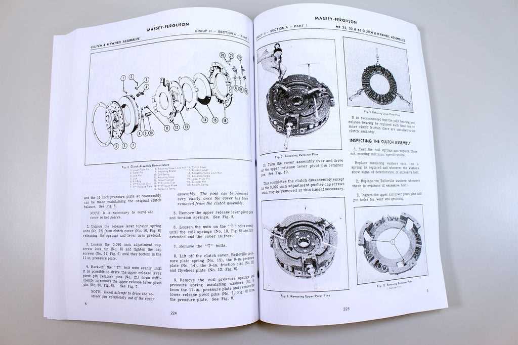
The hydraulic system plays a crucial role in the functionality of many machines. Key components such as hoses, seals, and pumps often need attention. Hoses transport fluid under pressure, making them susceptible to wear and tear. Seals prevent leaks, ensuring that the system maintains proper pressure. Lastly, pumps are vital for circulating hydraulic fluid, making their performance critical for overall operation.
Maintenance Tips for MF 65
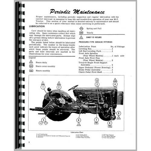
Proper upkeep of your agricultural machine is essential for optimal performance and longevity. Regular attention to various components not only ensures efficiency but also prevents costly repairs. Implementing a consistent maintenance routine can greatly enhance the functionality and reliability of your equipment.
Routine Checks
Conducting regular inspections is crucial. Look for wear and tear on belts, hoses, and other vital components. Keeping an eye on fluid levels is equally important to maintain smooth operations.
Cleaning and Lubrication
Regular cleaning of the exterior and accessible parts prevents dirt accumulation that could lead to issues. Additionally, appropriate lubrication of moving parts reduces friction and extends their lifespan.
| Task | Frequency |
|---|---|
| Check oil levels | Weekly |
| Inspect filters | Monthly |
| Clean air intake | Every 3 months |
| Lubricate moving parts | Every 100 hours |
Where to Find Parts Online
Locating components for your machinery can often be a daunting task, especially when you need reliable sources. Fortunately, the internet provides a multitude of options for sourcing the necessary items. Whether you’re looking for OEM selections or aftermarket alternatives, various platforms can meet your needs effectively.
Online Retailers
- Amazon – A vast marketplace with a range of options.
- eBay – Great for both new and used components.
- Specialized websites – Numerous sites focus on agricultural machinery supplies.
Forums and Communities
Engaging with online communities can be invaluable. Here are some ways to connect:
- Discussion boards – These often have sections dedicated to sourcing parts.
- Social media groups – Platforms like Facebook feature groups where enthusiasts share leads.
- Trade shows – Virtual events can also provide connections to suppliers.
Understanding the Assembly Process
The assembly process is a crucial phase in the production of machinery, ensuring that each component fits together seamlessly to create a fully operational unit. This intricate procedure involves meticulous planning and execution, as well as a deep understanding of how individual elements interact within the larger system.
Components are typically organized and categorized based on their function, facilitating a systematic approach to assembly. Technicians must be aware of the specifications and tolerances for each piece, as even minor discrepancies can lead to significant issues in performance and durability.
Moreover, proper sequencing during assembly is essential. Each step must be executed in a logical order, allowing for easy access to components and preventing potential damage to delicate parts. Regular checks and balances throughout this phase can help identify problems early, minimizing delays and ensuring a smooth transition from individual parts to a cohesive whole.
Finally, the use of visual aids can enhance understanding and efficiency. Clear illustrations or guides assist workers in navigating complex assemblies, reducing the likelihood of errors and promoting consistency across production lines.
Using Diagrams for Repairs
Visual representations are invaluable tools when it comes to maintaining and fixing machinery. They offer clear guidance, making it easier to identify components and understand their interconnections. Whether you’re a seasoned technician or a novice, these illustrations can simplify complex tasks and enhance overall efficiency.
Here are several benefits of utilizing these visuals during repair work:
- Clarity: Illustrations provide a straightforward view of each element, helping to eliminate confusion.
- Step-by-Step Guidance: Many visuals break down processes into manageable stages, allowing for systematic repairs.
- Error Reduction: By following a visual reference, the likelihood of making mistakes decreases significantly.
- Time Efficiency: Quick access to visual aids can speed up the troubleshooting process, saving valuable time.
To effectively use these resources, consider the following tips:
- Ensure the reference is clear and relevant to your specific model.
- Familiarize yourself with the layout before starting the repair.
- Use the visuals as a checklist to ensure all components are accounted for.
- Combine diagrams with written instructions for a comprehensive understanding.
Incorporating visual aids into your repair routine can transform the way you approach maintenance tasks, leading to more successful outcomes and improved machinery longevity.