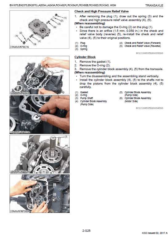
When working with heavy-duty machinery, having a clear understanding of its inner workings is crucial for maintaining performance and ensuring longevity. By exploring the key elements that make up the vehicle, operators can efficiently identify the different sections and their functions. Each part plays a specific role in ensuring smooth operation and reliable performance, especially in demanding tasks.
Detailed insights into component assembly provide a better understanding of how different sections interconnect. Knowing the layout and functionality of each part can save both time and resources during repairs or replacements. It’s essential to have a comprehensive guide that maps out these connections, enabling you to handle any maintenance work with precision and confidence.
With the right knowledge, you can tackle repairs more effectively, whether you’re dealing with simple adjustments or more complex overhauls. Properly identifying each component’s role within the system not only speeds up troubleshooting but also helps in selecting the appropriate replacements when necessary.
Exploring Key Components of Kubota BX2370
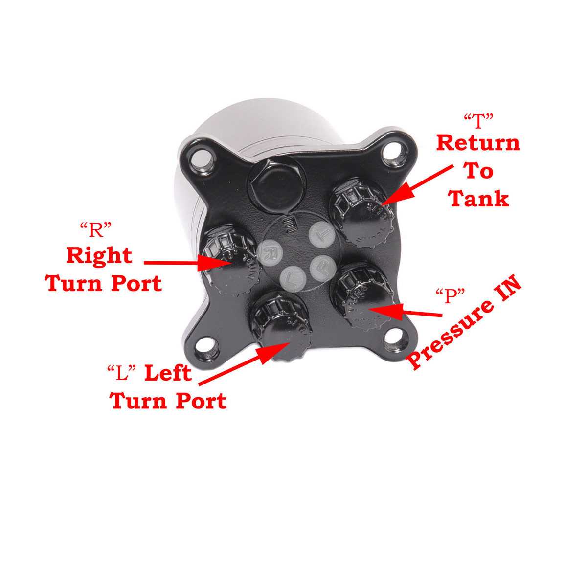
Understanding the core elements of a compact tractor is essential for proper maintenance and optimal performance. By examining its vital parts, users can gain insight into how the system functions as a whole. Each key component plays a specific role in ensuring the machine operates efficiently in various agricultural tasks.
Engine and Powertrain
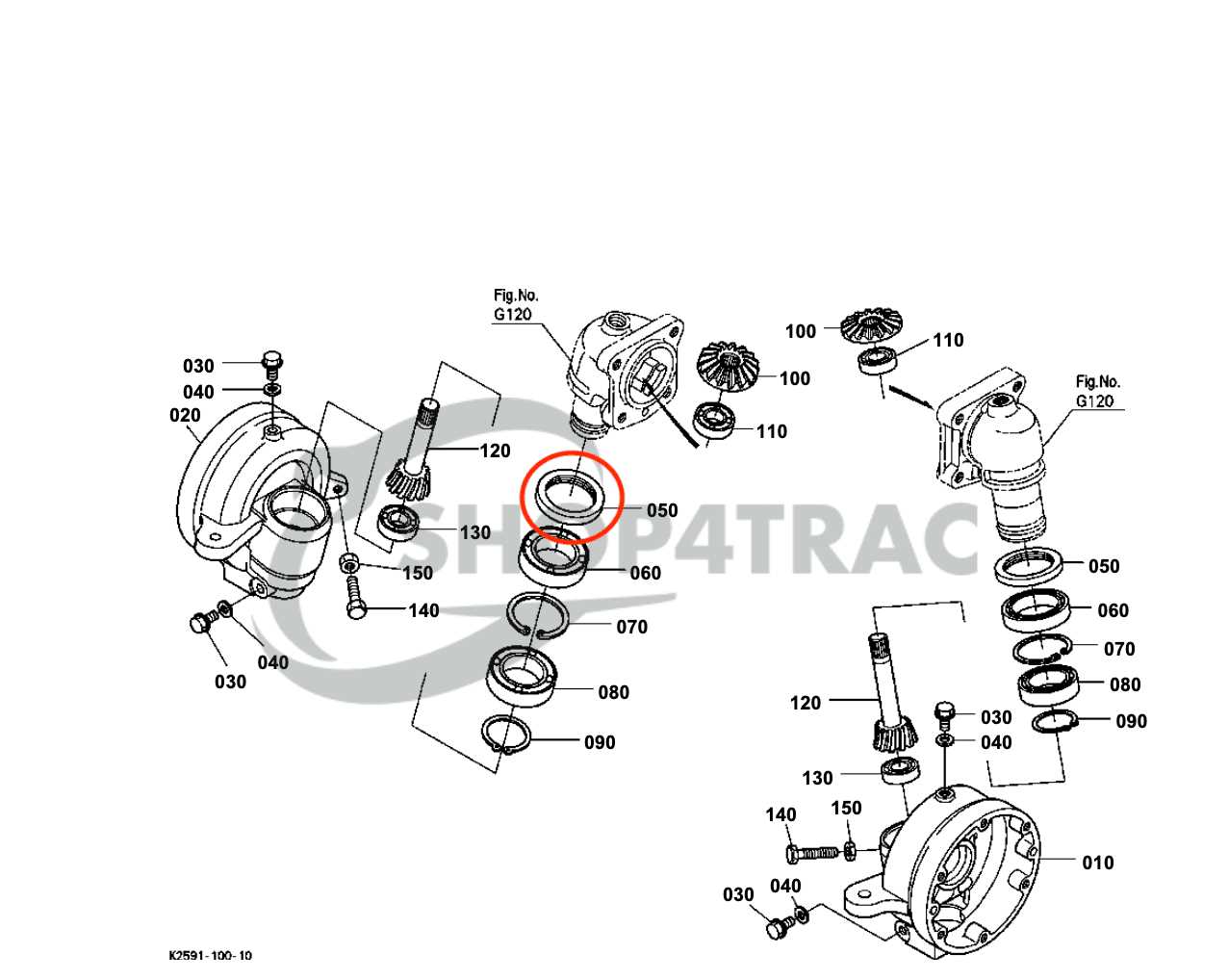
The engine and powertrain are the heart of any vehicle. In a small utility machine, these parts work together to provide the necessary force to perform a wide range of tasks. The engine’s efficiency is crucial for fuel economy and power output, while the powertrain ensures that the generated power is properly transferred to the wheels or attachments.
- Engine block
- Transmission system
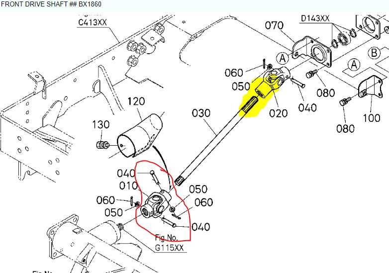
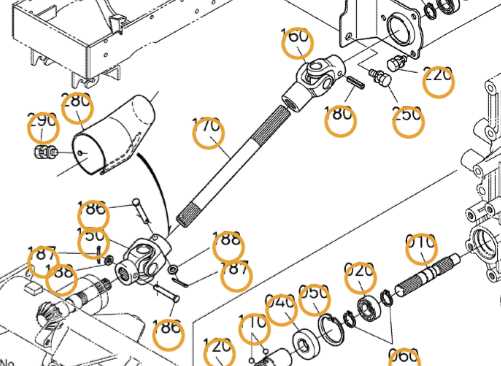
- Drive shaft
Hydraulic System
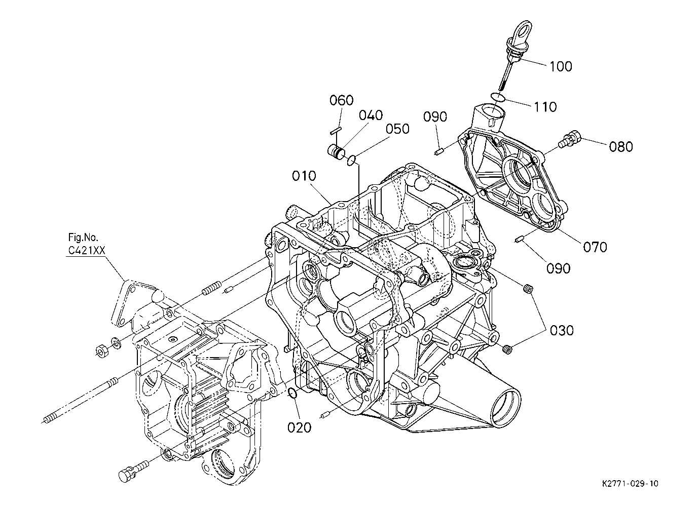
The hydraulic system is essential for powering attachments and other moving parts. It provides the necessary force to lift, lower, or move heavy loads. The components within this system must be well-maintained to ensure smooth operation without pressure loss or leaks.
- Hydraulic pump
- Hydraulic cylinders
- Hydraulic lines and hoses
Engine Assembly and Specifications
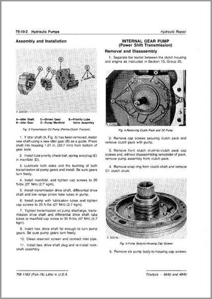
The engine assembly is a crucial component in any mechanical system, serving as the powerhouse that drives the entire machine. Understanding its structure and key specifications ensures proper maintenance and optimal performance. In this section, we will explore the main components of the engine and their functional aspects, offering a detailed look at how they interact to provide the necessary power for various tasks.
Key Components of the Engine Assembly
The core of the engine consists of several integral parts that work together to produce the required output. The cylinder block, crankshaft, and pistons are the primary elements, each designed to withstand high pressure and heat. The cylinder head and intake system play vital roles in regulating airflow and fuel delivery, ensuring efficient combustion. Meanwhile, the cooling system maintains optimal operating temperatures to prevent overheating during extended use.
Engine Specifications and Performance Metrics
Engine specifications include critical measurements such as displacement, horsepower, torque, and fuel efficiency. These values define the machine’s capabilities and determine its suitability for various tasks. The displacement, for example, refers to the total volume of air-fuel mixture an engine can process, while horsepower and torque indicate the power output and ability to perform heavy-duty work. Additionally, the engine’s fuel consumption rate is an essential factor in assessing long-term operational costs and efficiency.
Transmission System Breakdown
The transmission system of a compact utility vehicle plays a crucial role in the overall functioning of the machine. It facilitates the transfer of power from the engine to the wheels, enabling various speed and torque adjustments. Understanding the key components and their interactions is essential for proper maintenance and troubleshooting.
Main Components of the Transmission System
- Clutch Mechanism: Engages and disengages the power flow between the engine and the transmission.
- Gears: Allow different speed ratios to be selected, controlling vehicle speed and torque.
- Drive Shaft: Transfers rotational power from the transmission to the wheels.
- Hydraulic Pump: Provides the necessary pressure for shifting gears in certain systems.
Common Issues and Solutions
- Slipping Gears: Often caused by low fluid levels or worn-out components, leading to poor power transfer. Regular checks and fluid changes can prevent this.
- Hard Shifting: Could indicate problems with the linkage or gear synchronization. Proper lubrication and timely adjustments are essential.
- Unusual Noises: Grinding or whining sounds may suggest worn gears or bearings. Immediate inspection and part replacement can resolve this issue.
Hydraulic Parts Overview
The hydraulic system is essential for controlling various mechanical functions through the transfer of fluid pressure. This system plays a critical role in providing the necessary force for different components to operate smoothly. Understanding the layout and functionality of these components is vital for ensuring optimal performance and longevity.
Main Components of the Hydraulic System
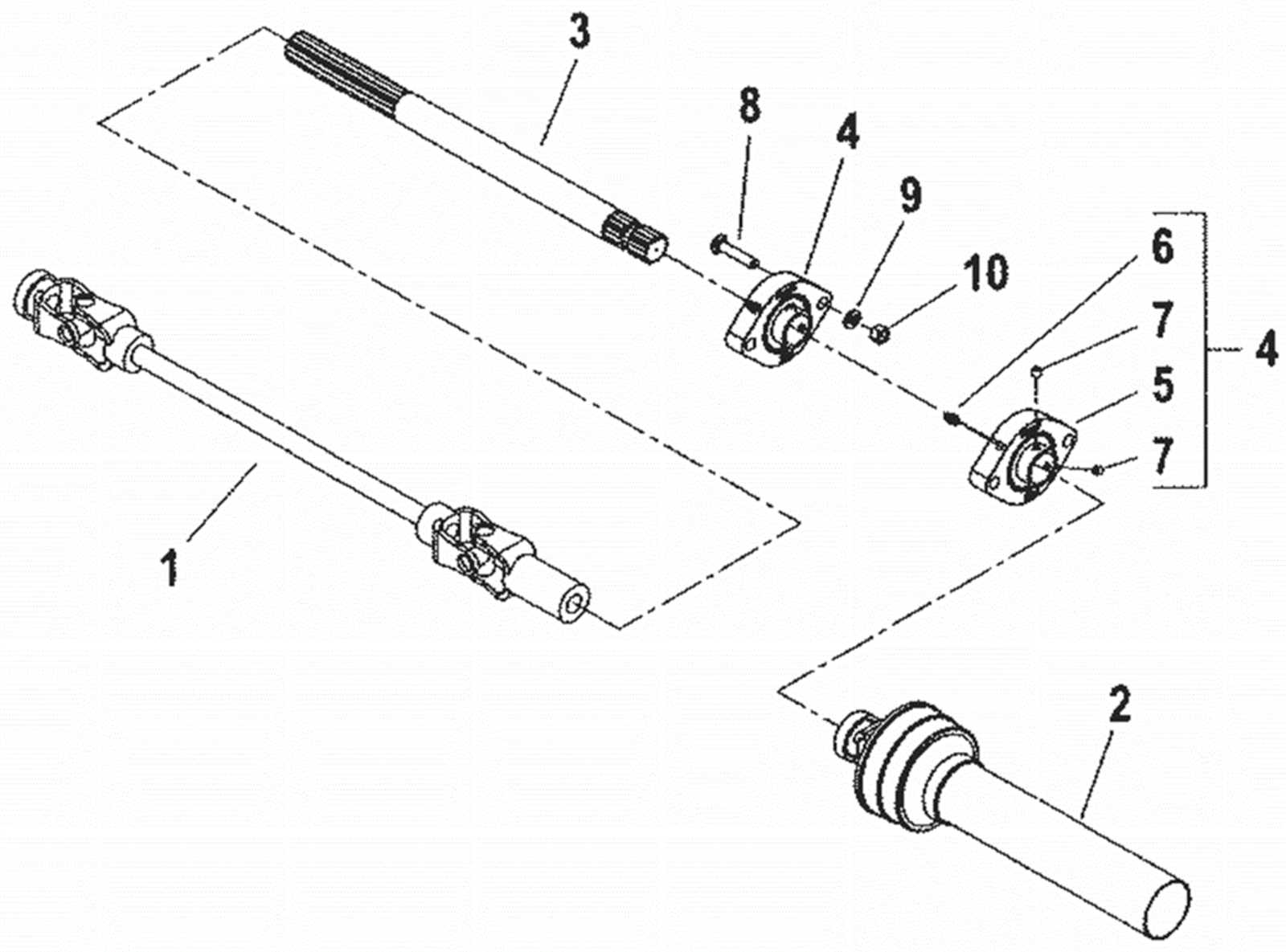
The hydraulic setup consists of several key elements that work together to enable efficient power transmission. Among these are the pump, cylinders, valves, and hoses. Each component has a specific role, from generating pressure to controlling fluid flow and executing motion.
Maintenance and Troubleshooting Tips

Regular maintenance of the hydraulic system is crucial for avoiding system failures. Ensuring that fluid levels are appropriate, inspecting hoses for wear, and keeping valves free from obstructions can significantly reduce the risk of issues. Additionally, identifying leaks or irregular pressure readings early can prevent costly repairs.
Understanding the Steering Mechanism
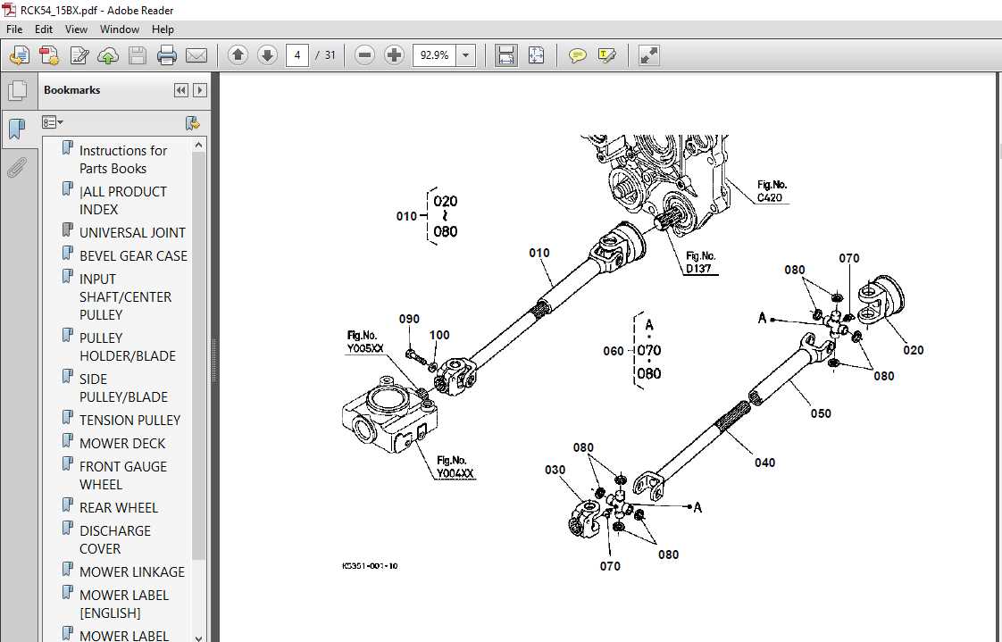
The steering system of a vehicle is a critical component that ensures smooth and controlled navigation. This mechanism is designed to translate the driver’s input into precise wheel movements, enabling the operator to guide the machine effectively across various terrains. A well-functioning steering system offers enhanced maneuverability, ensuring both stability and safety during operation.
Key Components of the Steering System
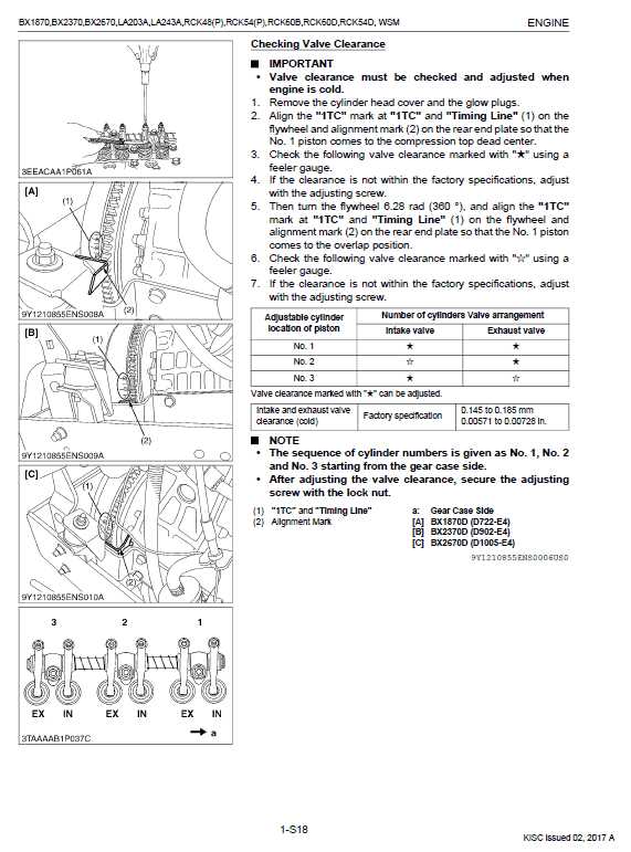
At the heart of the steering mechanism lies the steering wheel, which is connected to a set of gears and rods. These parts work together to convert the rotational motion of the wheel into directional movements of the wheels. The connection is facilitated by a series of joints and linkages, which ensure that the operator’s actions result in accurate turns. In addition, hydraulic or mechanical systems may be used to reduce the physical effort required to turn the wheel, making the system more responsive.
Maintaining the Steering System
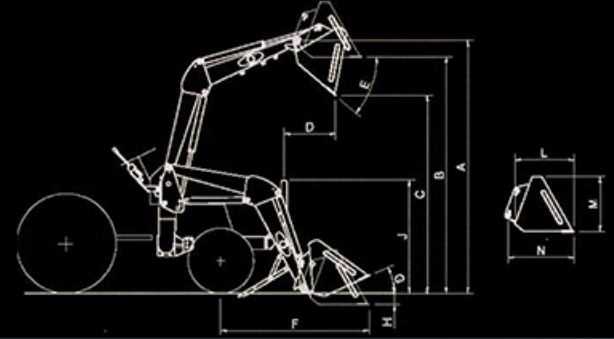
To ensure longevity and optimal performance, regular maintenance of the steering components is essential. Checking for signs of wear in the linkages, fluid levels in hydraulic systems, and ensuring all joints are properly lubricated will prevent malfunction. Over time, wear and tear can affect steering accuracy, so early detection of issues is crucial for safe operation.
Electrical System Diagram Explained
Understanding the layout of the electrical components in a machinery setup is essential for proper maintenance and troubleshooting. This section will break down the key elements involved in the power distribution and wiring systems that allow various functions to operate efficiently. The focus will be on how electrical connections are structured, how components interact, and the flow of power throughout the system.
Key Electrical Components
The electrical network consists of several vital parts that work in unison to provide the necessary power and control. These include the battery, alternator, fuses, switches, and connectors. Each component has a specific role in ensuring that electrical energy is available where it’s needed, and that safety measures are in place to protect the system from overloads.
Wiring and Power Flow
The wiring system connects each part and allows for the proper flow of current. The power distribution involves the flow from the battery, through the alternator for recharging, to various devices and circuits. Proper wiring ensures that each component receives the right amount of power at the correct time, minimizing potential disruptions.
| Component | Function |
|---|---|
| Battery | Stores and provides electrical energy to the system |
| Alternator | Charges the battery and powers electrical components when the engine is running |
| Fuses | Protects the system from electrical overload by interrupting the flow if necessary |
| Switches | Controls the on/off state of electrical devices |
| Connectors | Join electrical components, ensuring proper connections for power flow |
Wheel and Tire Configuration
The arrangement of wheels and tires plays a crucial role in the performance and stability of small utility vehicles. Proper alignment and tire selection ensure optimal traction, weight distribution, and overall functionality, making it essential to understand the various components involved. The configuration affects the vehicle’s handling, maneuverability, and adaptability to different terrains, allowing users to customize based on their specific needs.
Wheel size and tire type are key factors that influence the machine’s efficiency. The correct dimensions are necessary for maintaining balance, preventing undue stress on the frame, and ensuring a smooth ride over various surfaces. Additionally, selecting the appropriate tread pattern can enhance grip, particularly in off-road conditions.
Adjustments to rim width and tire pressure also contribute significantly to the vehicle’s performance. Proper inflation helps maintain consistent contact with the ground, while wider rims may be chosen for added stability or increased load-bearing capacity. These elements should be carefully considered to achieve maximum efficiency in diverse operational environments.
Fuel and Exhaust System Layout
The fuel and exhaust system of a compact utility vehicle plays a crucial role in its overall performance and efficiency. These systems ensure the proper flow of fuel to the engine and the safe expulsion of gases after combustion. A well-designed layout is essential for optimal functionality and longevity of the machine.
Fuel System Configuration
The fuel system is designed to provide the engine with a consistent supply of fuel for efficient combustion. It typically includes components such as the fuel tank, filter, pump, and injector system. Each part works together to ensure that the fuel is properly filtered, pressurized, and delivered to the engine at the correct rate, maintaining smooth operation.
Exhaust System Setup
The exhaust system is responsible for directing and controlling the flow of gases produced during combustion. It includes a network of pipes, a muffler, and sometimes a catalytic converter. These components work together to reduce noise and minimize harmful emissions, ensuring the vehicle operates within environmental regulations.
Maintaining the Safety Features
Ensuring that all protective elements on your machinery are functioning properly is crucial for the safety of the operator and those nearby. Regular inspection and maintenance of safety mechanisms help prevent accidents and extend the lifespan of the equipment. These systems are designed to protect users from potential hazards, such as moving parts, heat, and electrical malfunctions, so keeping them in top condition should be a priority.
Here are some essential safety features to regularly inspect and maintain:
- Safety switches: Verify their correct operation to ensure the machine will not start unexpectedly.
- Operator presence sensors: Test to make sure they detect the operator’s position and shut down the machine if needed.
- Guarding systems: Check for any damage or wear to the shields and covers that protect moving parts.
- Braking mechanisms: Ensure that brakes are functioning efficiently to stop the machine promptly in an emergency.
Incorporating these checks into your routine maintenance will help reduce risks and improve the overall performance of your equipment.