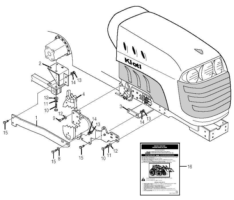
Understanding the detailed arrangement of various mechanical elements is essential for ensuring smooth maintenance and repair processes. These layouts provide a clear visual reference for locating specific components within the system, which is invaluable when identifying replacement parts or troubleshooting mechanical issues.
Each section offers an organized structure, making it easier to navigate through different assemblies. Whether you’re handling routine maintenance or addressing specific repairs, having access to precise visual breakdowns ensures that you approach the task efficiently and accurately.
Clear diagrams not only enhance understanding but also minimize errors during complex procedures. With all elements laid out in an intuitive format, the task of identifying, replacing, or servicing components becomes much more straightforward.
Understanding Kioti Parts Schematics
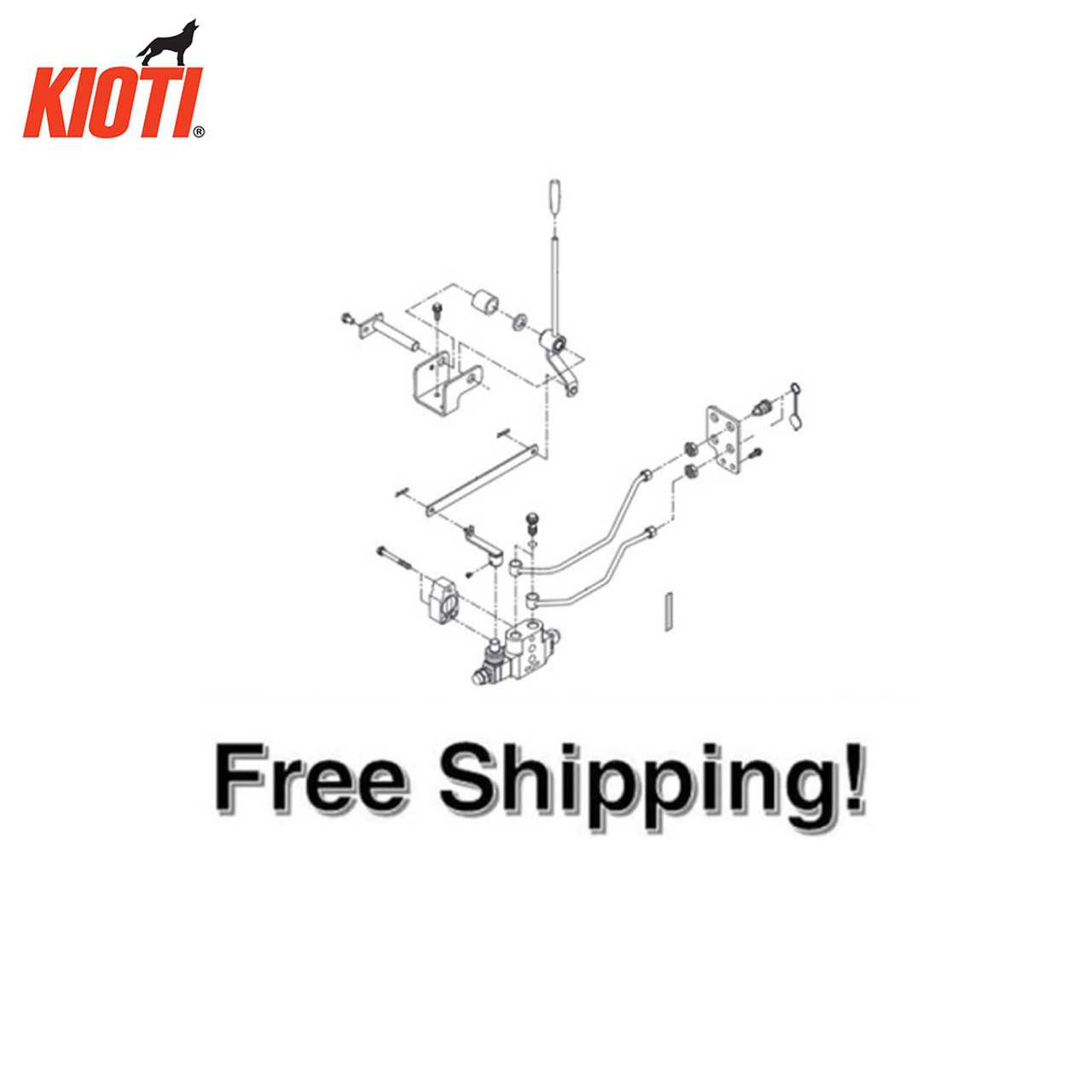
Mechanical schematics offer a detailed view of how various components fit and function together in a machine. By analyzing these layouts, you can identify individual elements, their locations, and how they connect to each other. The structured layout simplifies repairs and maintenance tasks, helping to pinpoint issues quickly and understand assembly procedures.
- Visual representation of mechanical systems
- Component arrangement and their interactions
- Efficient troubleshooting through logical connections
Comprehending these drawings allows users to gain a deeper insight into the mechanics, ensuring that repairs and replacements are handled accurately and efficiently.
How to Read a Kioti Diagram
Understanding technical drawings can help in identifying the proper components and their arrangement within machinery. These visual guides use simplified representations to show how individual elements are connected and how they function together as a whole.
Symbols and Labels: Each drawing includes specific symbols and labels to indicate individual components. By familiarizing yourself with these symbols, you’ll be able to quickly identify each element and its role.
Lines and Arrows: Lines and arrows serve to depict the flow or connection between various elements. Following these lines will give a clear understanding of how different components interact.
Reference Numbers: Most technical drawings will include reference numbers for each part. These numbers can be cross-referenced with a list or catalog to provide detailed information about the component’s name and specifications.
Essential Components in Kioti Tractors
Modern agricultural vehicles are designed to handle a variety of tasks, each requiring specific tools to operate efficiently. These machines rely on a combination of critical elements that work together to ensure durability, power, and functionality in diverse environments.
Engine and Transmission
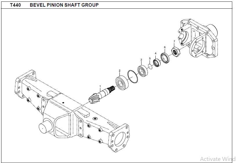
The core of any farming vehicle is its engine, which provides the necessary power for heavy-duty tasks. The transmission system, meanwhile, is responsible for adjusting speed and torque, allowing the vehicle to perform optimally under different conditions. Together, these systems form the backbone of the machine’s overall performance.
Hydraulic System and Implements
A well-functioning hydraulic system is essential for controlling attachments, enabling smooth operation of equipment such as loaders, mowers, and other accessories. This system allows for precise control and ease of use, making it vital for both productivity and ease of operation.
Exploring Hydraulic System Layouts
Understanding the arrangement of hydraulic components is essential for efficient operation and maintenance of machinery. By analyzing how different elements connect and interact, users can optimize performance and troubleshoot potential issues.
Main Components of the Hydraulic Layout
- Pump: Provides the necessary flow of fluid to drive the system.
- Valves: Regulate the direction, pressure, and flow rate of the hydraulic fluid.
- Cylinders: Convert hydraulic energy into mechanical force.
- Hoses and Fittings: Transport fluid between different components.
Key Considerations for Efficient Layout
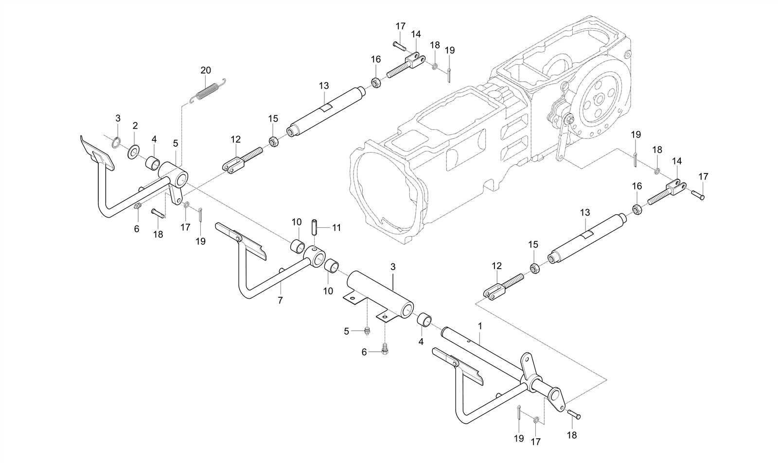
- Ensure proper fluid flow to prevent pressure loss.
- Minimize the length of hoses to reduce inefficiencies.
- Use quality components to ensure system durability.
Identifying Electrical System Parts
The electrical components of a machine are critical for its proper functioning. Recognizing these elements and understanding their roles helps ensure the system runs efficiently and safely.
- Battery: Provides the initial power to start the machine and supports all electrical circuits.
- Alternator: Responsible for generating electricity and charging the battery while the machine is running.
- Fuses: Protect the electrical circuits from overloads by breaking the connection if excess current flows through.
- Starter: Engages the engine’s crankshaft to initiate operation.
- Wiring harness: A collection of wires that connect all electrical components, ensuring efficient communication throughout the system.
By identifying these key elements, users can troubleshoot and maintain the electrical system more effectively.
Maintaining Your Tractor Using Diagrams
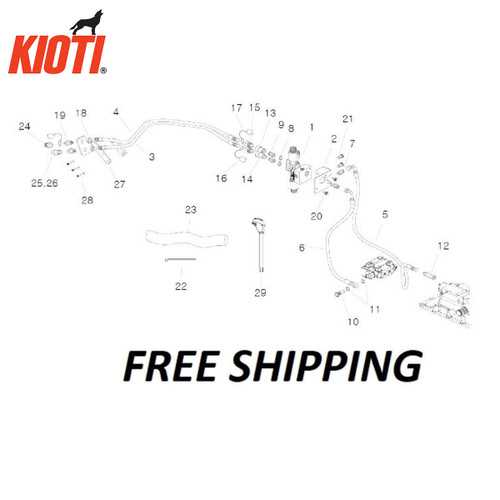
Proper upkeep of your agricultural vehicle is crucial for optimal performance and longevity. Utilizing visual representations can greatly assist in understanding the various components and systems within your machine. These illustrations serve as valuable tools, guiding you through maintenance procedures and repairs effectively.
Understanding Components
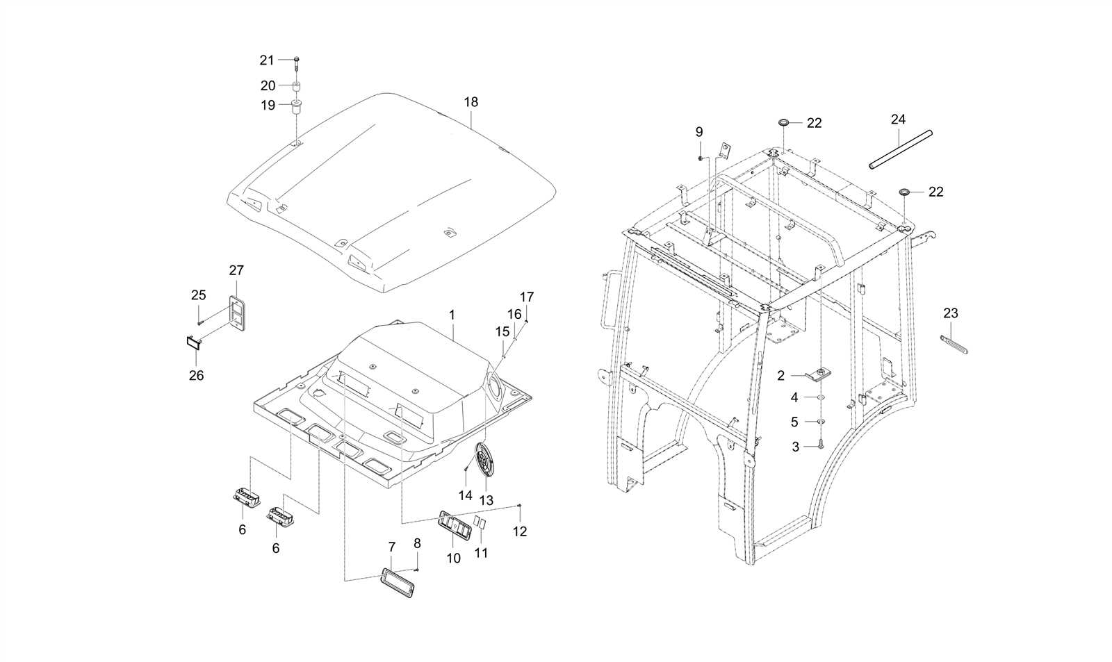
Visual aids provide clarity on the different parts of your vehicle, making it easier to identify where maintenance is needed. By familiarizing yourself with the layout and function of each section, you can efficiently address issues as they arise, ensuring that your equipment remains in peak condition.
Improving Maintenance Procedures
By consulting these visual guides, you can streamline your maintenance routines. Step-by-step instructions paired with diagrams enhance your ability to perform tasks such as oil changes, filter replacements, and general inspections. This method not only saves time but also reduces the likelihood of errors during servicing.
Replacing Key Engine Components
Maintaining optimal performance in machinery often requires the replacement of essential engine elements. Understanding the procedure for swapping out these components is vital for ensuring longevity and efficiency. This section outlines the process and considerations involved in upgrading critical engine parts, which can enhance overall functionality.
Identifying Components for Replacement
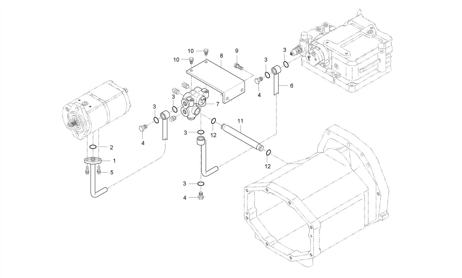
Before beginning any replacement procedure, it’s important to accurately identify which components need attention. Regular inspections and diagnostic assessments can reveal signs of wear and tear, helping to determine when a part is due for replacement. Common components that may require replacing include gaskets, filters, and belts, each of which plays a crucial role in engine operation.
Steps for Component Replacement
Once the components are identified, follow these general steps for effective replacement:
| Step | Action |
|---|---|
| 1 | Gather necessary tools and replacement components. |
| 2 | Disconnect power sources to ensure safety during replacement. |
| 3 | Remove the old component, taking care to avoid damage to surrounding parts. |
| 4 | Install the new component, ensuring a secure fit and proper alignment. |
| 5 | Reconnect power sources and perform a functionality test to verify installation. |
Common Issues with Kioti Parts
When it comes to machinery components, various challenges can arise, affecting overall performance and efficiency. Understanding these common problems can help in identifying solutions and maintaining optimal operation.
Some frequent complications include:
- Wear and Tear: Over time, components may experience degradation due to regular usage, leading to decreased functionality.
- Compatibility Issues: Using non-compatible elements can result in malfunctions or reduced performance.
- Installation Errors: Improper installation can cause immediate failures or long-term damage to the system.
- Environmental Factors: Exposure to harsh conditions can adversely affect the durability and lifespan of various components.
Addressing these challenges promptly can enhance the longevity and reliability of your machinery.
Using Diagrams for Troubleshooting
Visual representations play a crucial role in diagnosing issues within machinery and equipment. They serve as valuable tools, enabling users to identify components and their relationships systematically. By utilizing these illustrations, one can efficiently pinpoint malfunctions and devise effective solutions.
When encountering operational challenges, referring to these visual guides can simplify the troubleshooting process. They help users understand the layout and functionality of different elements, making it easier to isolate problems. Additionally, these resources often provide insight into the assembly and disassembly procedures, which can be essential for effective repairs.
In complex systems, clear visual aids significantly enhance comprehension and retention of information. They allow individuals to follow logical sequences and understand the interactions between various parts. By leveraging these resources, users can approach maintenance tasks with confidence, ensuring a more efficient resolution to any issues encountered.